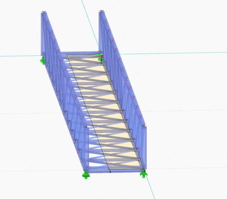
This section uses the example of the cables on the left side of the bridge to show you how to create a member load from a surface load. To do this, select the Cable on Left load case in the toolbar. The surface load of 1.5 kN/m² refers to the left 40% of the bridge.
Defining Corner Nodes of Surface
To be able to enter the surface to which the load relates, new nodes must be defined on the bottom transverse frame. To do this, select both members and open the "Divide Member Using Distance" dialog box. Depending on the definition direction of the members, enter 40% at the member start or the member end.
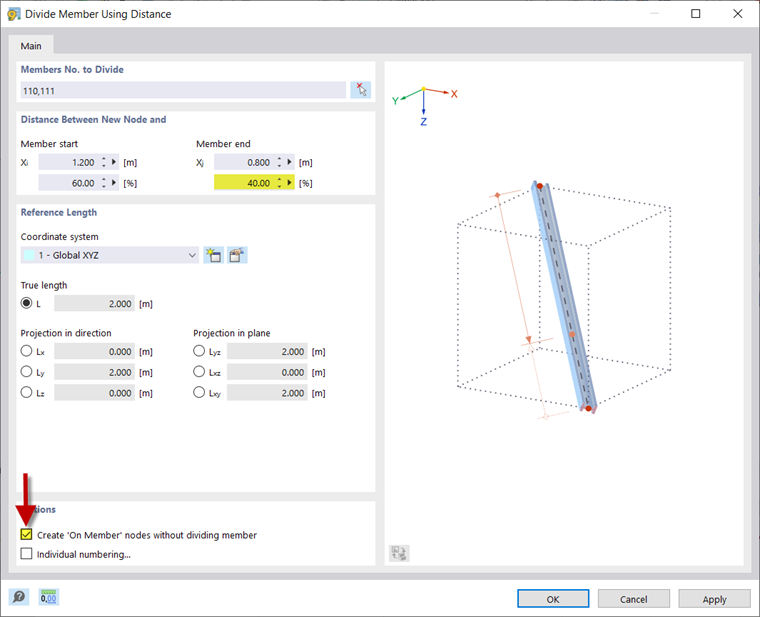
To enter the cables and the walkway on the right side of the bridge, another subdivision of the bridge is required.
To do this, create a node on both bottom members of the transverse frame at a distance of 30% to the right side of the bridge.
Creating Surface Load
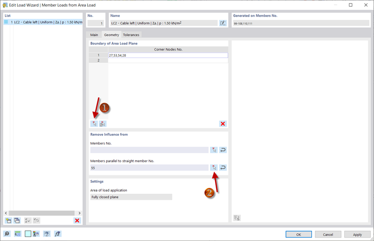
RFEM 6 and RSTAB 9 provide the option to generate a member load from a surface load using the Load Wizard. Double-click the corresponding entry in the Navigator to open the "New Load Wizard | Member Loads from Surface Loads" dialog box. Here you can enter the load size, which is 1.5 kN/m² in the example, and select the corner nodes of the surface in the "Geometry" tab using the
![]() button.
button.
To exclude members from the load effect, there is the "Remove Influence from" section. For example, if you select a member of the bottom chord for the "members parallel to straight member No.", the load is only applied to the transverse beams and not to the bottom chords.
The load of the walkway can be entered in the same way. Set the corresponding load case, enter 3 kN/m as the load size, and select the nodes on the right side of the bridge as corner points.