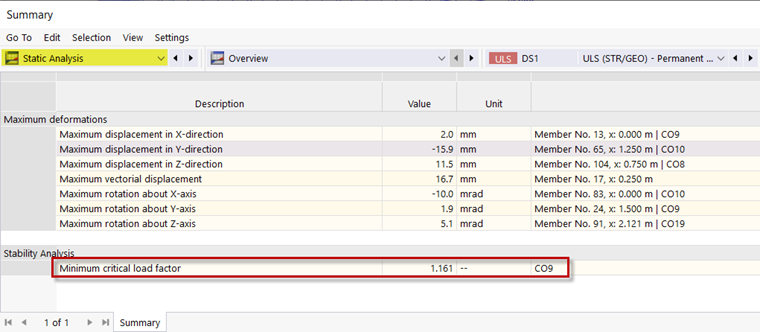
The stability analysis in RFEM 6 and RSTAB 9 allows you to calculate the minimum critical load factor and the effective lengths of the individual members. You can also graphically display the governing mode shape. Since you already activated the stability analysis when setting up the combination wizard, you can now also see the results of this analysis. After the calculation, the "Static Analysis" category opens in the table, where you can find the minimum critical load factor.
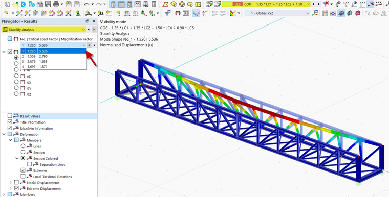
This critical load factor occurs in Load Combination 8, which can be selected in the toolbar. Thus, you obtain the results for this load combination only. If you select "Stability Analysis" in the "Results" tab in the Navigator, you can display various mode shapes.
Instability Remedy
Since the critical load factor is less than one, the bridge is unstable in the current state of the example. You can avoid this by inserting a transverse frame in the middle of the bridge and thus reducing the buckling length.
The calculated results can be shown or hidden using the
![]() button.
button.
To do this, remove the hinges on the transverse beam in the middle of the truss bridge and select a "Beam" member as the member type for the central posts. You can also change the alignment of the posts by specifying 90° as the rotation angle in the "Section" tab.
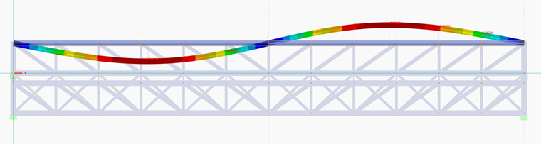
After recalculating Design Situation 1, you obtain a minimum critical load factor of 1.16 in Load Combination 9. As you can see in the mode shape for this load combination, the top chord is now forced into a double-wave deformation.
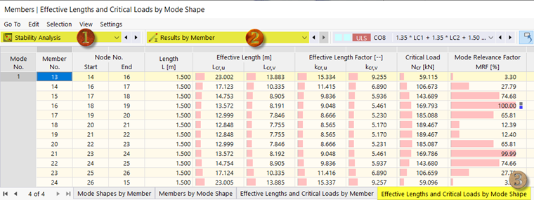
Effective Lengths
The effective lengths are listed in the table under "Stability Analysis" in the "Results by Member" category, the "Effective Lengths and Critical Loads by Mode Shape" tab.
Use the
![]() button to display the objects selected at the time. Only the results of the selected objects are then listed in the table.
button to display the objects selected at the time. Only the results of the selected objects are then listed in the table.
If you select the top chord on the right and use it to define the visibility, you can see the effective lengths for the associated members directly in the table. They refer to the main axes u and v of the cross-section.
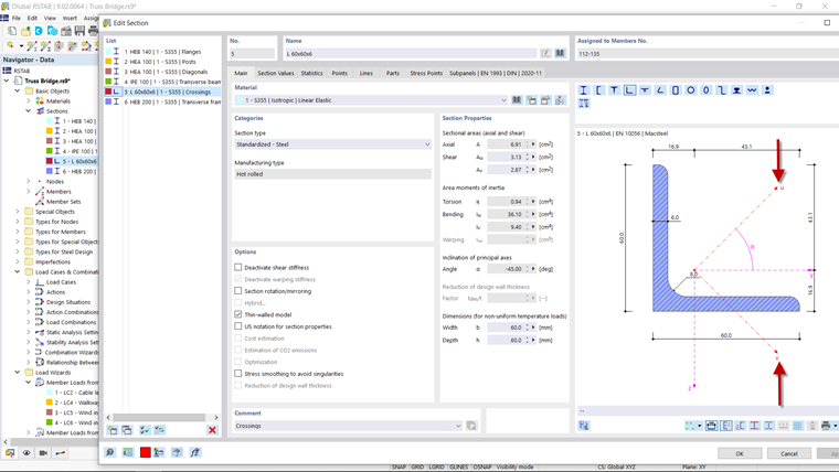
If you are not sure about the direction of the cross-section's principal axes, open the "Edit Cross-Section" dialog box by double-clicking the respective cross-section in the Navigator. The principal axes are shown in the cross-section image.