Home Downloads & Info References Customer Projects New Construction for Bus Station in Aarau, Switzerland
New Construction for Bus Station in Aarau, Switzerland
Customer Project
This article was translated by Google Translator
A unique structure which roofs the main bus station in the Swiss town of Aarau was built at the end of 2013. The canopy has a cloud-like shape and contains the largest single-chamber cushion in the world. It has a volume of 1810 m 3 and a roofed area of 1070 m 2 .
Structural Engineering |
Structural engineering, workshop planning steel, foil, cables, construction management + quality control formTL Ingenieure für Tragwerk und Leichtbau GmbH, Radolfzell www.form-tl.de |
Construction |
Project Planning and Solid Construction suisseplan Ingenieure AG Aarau, Switzerland www.suisseplan.ch Construction Work Arge Foliendach mit Ruch AG Altdorf, Switzerland ruch.ag Vector Foiltec GmbH, Bremen, Germany www.vector-foiltec.com |
Architect |
Vehovar & Jauslin AG Zürich, Switzerland www.vja.ch |
Investor |
City of Aarau, Switzerland www.aarau.ch |
- Length: ~ 42 m
- Width: ~ 39 m
- Height: ~ 29.5 ft
- Nonlinear Effects: cable
- Number of Nodes: 6,796
- Members: 9,545
- Cross-Sections: 5
Model
Structure
The external dimensions of the roof are l x w = ~ 138 ft x ~ 128 ft. The eave height is 23 ft. In the center of the canopy there is an organically shaped opening. The air cushion is inflated and reaches a height between 4.3 ft and 10.5 ft. Furthermore, a clear and blue‑dyed foil with a finely balanced print was used.
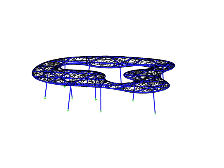
The cushion is enveloped and spanned by an irregular mesh of stainless steel cables that are fixed to the curved pipes on the edge. The edge beams are supported by a load bearing system consisting of steel girders lying within the cushion.
The entire technical infrastructure for water, air, electronics and sensor technology has been integrated into the inner steel structure.
The roof is supported by a total of 11 filigree columns made of round pipes with a diameter of d = 11 3/4 in that are slightly inclined in an axis. The "cloud" seems to float. The ETFE cushion has such an airtight and energy‑saving design that merely 15 % of the forecast air power needed to sustain the structure is required.
Immediately after the bus station was put into service, it became an exhibit in the Swiss architectural trade show "architektur 0.13" in Zürich.
Contact us
Do you have questions or need advice?
Contact our free e-mail, chat, or forum support or find various suggested solutions and useful tips on our FAQ page.
Recommended Events
Eurocode 3 | Steel structures according to DIN EN 1993-1-1
Online Training 6 May 2021 8:30 AM - 12:30 PM CEST
Stability Design in Steel Construction with RFEM and RSTAB
Webinar 1 December 2020 2:00 PM - 2:45 PM CET
Designing Cold-Formed Steel Sections According to Eurocode 3
Webinar 30 April 2020 3:00 PM - 3:45 PM CEST
Membrane Structures with Wind Loads From CFD Wind Simulation
Webinar 24 March 2020 3:00 PM - 4:15 PM CET
Videos
Models to Download
Knowledge Base Articles

New
In RF-/FOUNDATION Pro, the user can freely select the proportion of the relieving soil pressure by means of the factor kred.Screenshots
Product Features Articles

SHAPE-THIN determines the effective cross-sections according to EN 1993-1-3 and EN 1993-1-5 for cold-formed sections. You can optionally check the geometric conditions for the applicability of the standard specified in EN 1993‑1‑3, Section 5.2.
The effects of local plate buckling are considered according to the method of reduced widths and the possible buckling of stiffeners (instability) is considered for stiffened sections according to EN 1993-1-3, Section 5.5.
As an option, you can perform an iterative calculation to optimize the effective cross-section.
You can display the effective cross-sections graphically.
Read more about designing cold-formed sections with SHAPE-THIN and RF-/STEEL Cold-Formed Sections in this technical article: Design of a Thin-Walled, Cold-Formed C-Section According to EN 1993-1-3.
Frequently Asked Questions (FAQ)
-
Can I export my cutting pattern?
- I am trying to manually check the deformations from the CRANEWAY add-on module. However, I obtain great deviations. How to explain the differences?
- What should be considered when using a failure of columns under tension in the RF‑/DYNAM Pro – Equivalent Loads add-on module?
- Why is there no stability analysis displayed in the results despite the activation of the stability analysis in RF‑/STEEL EC3?
- How can I model and design a crane runway girder with Dlubal Software?
- How do I model a suspended membrane roof structure with line supports?
- Is it possible to set user-defined values when viewing solid stress results?
- How do I model a tent roof with two cone tips?
- Why do I get large differences for the design of a longitudinally stiffened buckling panel in comparison with the German and Austrian National Annex?
- How are the signs for the release results of a line release and line hinges interpreted?
Customer Projects
Programs Used for Structural Analysis