Marie Curie School Timber-and-Steel Structures' Preliminary Design in Fontoy, France
Customer Project
![[FR] CP 001178 | Marie Curie School’s Timber and Steel Structures Preliminary Design in Fontoy, F...](/-/media/Images/netgenium/thumbnails/2/9/6/4/5/2964550/2964550.png?la=en&mw=578&mlid=FCDA24F16FEA4C37B9C54EC1BE1CC0F0&hash=BB9E5589F2E0B00B8DF448A494348EB8DD25E2C2)
[FR] CP 001178 | Marie Curie School’s Timber and Steel Structures Preliminary Design in Fontoy, F...
-
01
Architect's View of Marie Curie College in Fontoy (© KL Architectes - Bagard & Luron)
-
01
Timber Frame Model of School Entrance in RFEM (© BET Moselle Bois)
-
01
RFEM Model of Bicycle Shelter (© BET Moselle Bois)
-
01
© KL Architects - Bagard & Luron
-
01
Bike Room at Marie Curie College in Fontoy, France
-
01
Bike Room at Marie Curie College in Fontoy, France
-
02
Timber Frame Model of School Entrance in RFEM (© BET Moselle Bois)
-
02
Architect's View of Marie Curie College in Fontoy (© KL Architectes - Bagard & Luron)
-
02
RFEM Model of Bicycle Shelter (© BET Moselle Bois)
-
02
© KL Architects - Bagard & Luron
-
02
Bike Room at Marie Curie College in Fontoy, France
-
03
RFEM Model of Bicycle Shelter (© BET Moselle Bois)
-
03
Architect's View of Marie Curie College in Fontoy (© KL Architectes - Bagard & Luron)
-
03
Timber Frame Model of School Entrance in RFEM (© BET Moselle Bois)
-
03
© KL Architects - Bagard & Luron
-
03
Bike Room at Marie Curie College in Fontoy, France
The general contractor Demathieu Bard Construction commissioned Dlubal customer BET Moselle Bois to carry out the timber-and-steel structures' preliminary design. The projects are part of the Marie Curie School located in Fontoy, in the Moselle district.
Owner |
Moselle District, France Official Site |
Architect |
KL Architectes, Metz, France www.kl-architectes.fr Bagard & Luron Architectes, Nancy, France |
Structural Design |
BMB-BET Moselle Bois, Saint Julien Lès Metz, France www.bet-moselle-bois.fr |
General Contractor |
Demathieu Bard Construction, Montigny-lès-Metz, France www.demathieu-bard.fr |
RFEM Data for the Bicycle Shelter
Model
New School Building Entrance
The wood structure of the school’s entrance is a half glued-laminated timber frame. Web plate connections were used between the posts and the rafters. In the upper section, the rafters are supported at one end on a concrete wall.
The timber posts include a pinned support to the concrete floor with members spanning each post.
A longitudinal beam further supports the roof purlins.
New Bicycle Shelter
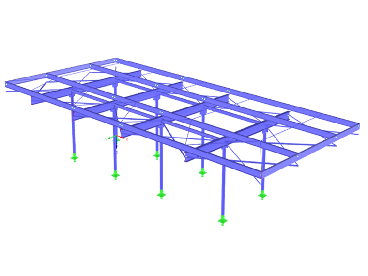
The bicycle shelter includes a steel frame with circular columns pinned at the ground level. The purlins and rafters are I-sections. The columns are rigidly connected to the rafters. An I-section plate is welded at the top of the column to secure the connection with the purlins.
The frames are oriented in the longitudinal direction and the purlins are fixed on each side.
A vertical slat cladding at the roof level is attached to the top purlins and bottom plates.
Structural Design
BET Moselle Bois carried out the 3D frame preliminary design utilizing RFEM structural analysis software. The required designs according to Eurocode 5 for the timber structure and Eurocode 3 for the steel structure were performed with the RF-TIMBER Pro and RF-STEEL EC3 add-on modules.
Project Location
Rue de Verdun57650 Fontoy
France
Write Comment...
Write Comment...
Contact Us
Do you have any further questions or need advice? Contact us via phone, email, chat or forum or find suggested solutions and useful tips on our FAQ page, available 24/7.

New
Evaluating and Documenting Steel Joints Analysis Results in RFEM 6
With the RFEM 6 add-on Steel Joints, you can analyze steel connections by using an FE model. This article demonstrates how to evaluate and document the steel joints analysis results.

New
- The design of the connection components is performed according to Eurocode EN 1993-1-8
- After activating the Add-on, the design situations for Steel Connections must be activated in the "Load cases and Combinations" dialog box
- For the design of the connection stability (Buckling), it is necessary to have the Add-on Structure Stability activated
- The calculation can be started via the table or via the icon in the top bar
- Why the results of members and set of members differ in the design?
-
How do I set a release for warping?
- How can I define a warping spring or a warping restraint?
- At which point on a cross-section are the supports and loads assumed for the calculation with warping torsion?
- The limit stress is activated, but my stress ratio is “non-designable” in the Stress-Strain Analysis add-on. What could be the reason?
- How can I define a warping spring or a warping restraint?