


Designer
The structure is made of French glued-laminated timber, defined mainly by its essence and color, providing a soothing perspective of lightness. It contains two indoor tennis courts and a locker room area sheltered by timber frame walls.
The hall is built on shaft foundations connected by stringers supporting the isolated steel cladding and Trespa panels. The exterior carpentry is made of aluminum enhanced by insulating safety glazing; resin on asphalt was additionally used to establish the court's floor. The entire structure is coated by a sandwich panel covering system, brightened by solar panels and highlighted by a strip of translucent polycarbonate panels also acting as an efficient lighting source, providing natural daylight within the hall and throughout the playing areas.
One specific feature defining this project is the location of the tennis courts. They are oriented within the load-bearing direction of the central frame, which stands as the prevailing aspect of the structure. The three-hinged frame is made of curved glued-laminated timber expanding over 37 m (121.39 ft).
The frames, stabilized by the supporting purlins spreading over 18 m (59.06 ft), efficiently abide by the constraints enacted within the building permit as well as within the French Tennis Federation regulations, which are detailed below; specifically, they require a free height of 7 m (22.97 ft) beneath the ceiling.
Technical Constraints
The sports management of the French Tennis Federation recommends a playing surface of 18 m x 36 m (59.06 x 118.11 ft). This surface integrates the playing area, which is a rectangle with a length of 24 m (78.74 ft) and width of 11 m (36.09 ft), as well as a setback of about 6 m (19.69 ft) behind each baseline and a clearance of about 3.5 m (11.48 ft) on each side to allow the players to hit the ball without hindrance.
The layout of the hall and its frame shape comply with the regulatory standards with an envelope of approximately 37 m x 37 m (121.39 ft x 121.39 ft) covering the two tennis courts with a clear height of 7 m (22.97 ft).
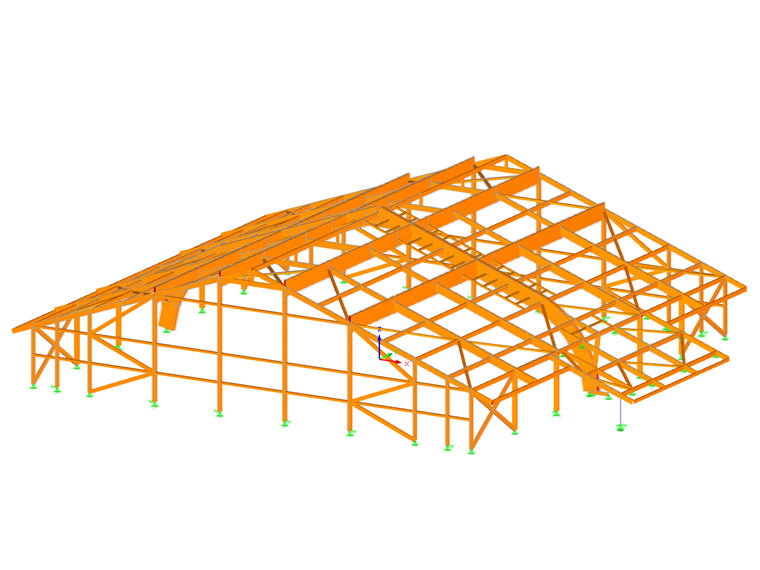
Structural Design Software
RFEM software was used to carry out the structural design. The entire timber structure and the arched frame were designed according to Eurocode 5 using the RF-TIMBER Pro add-on module.
The timber parts, bolts, and metal plates of the fastening of the central frame legs were designed with the RF‑JOINTS Timber – Steel To Timber add-on module.
The structure is an X-type building of the 5th category located in seismic zone 4 (medium). This required seismic design was performed using the add-on modules RF‑DYNAM Pro – Natural Vibrations and RF‑DYNAM Pro – Equivalent Loads.
The steel beams were designed according to Eurocode 3 using the RF‑STEEL EC3 add-on module.
| Location | Montmélian, France |
| Investor | City of Montmélian, France |
| Architect | Agence Morin Rouchère, L'Haÿ-les-Roses |
| Structural Design | CBS, Choisy-le-Roi |
| Timber Frame | Lifteam, La Rochette |


