


Dlubal customer m3-ZT GmbH performed the structural analysis and design of the tower, including the planning and calculation of the construction details. They utilized RFEM for the structural analysis and design. Additionally, the engineers from m3-ZT supported the assembly at this incredible height.
Structure and Design
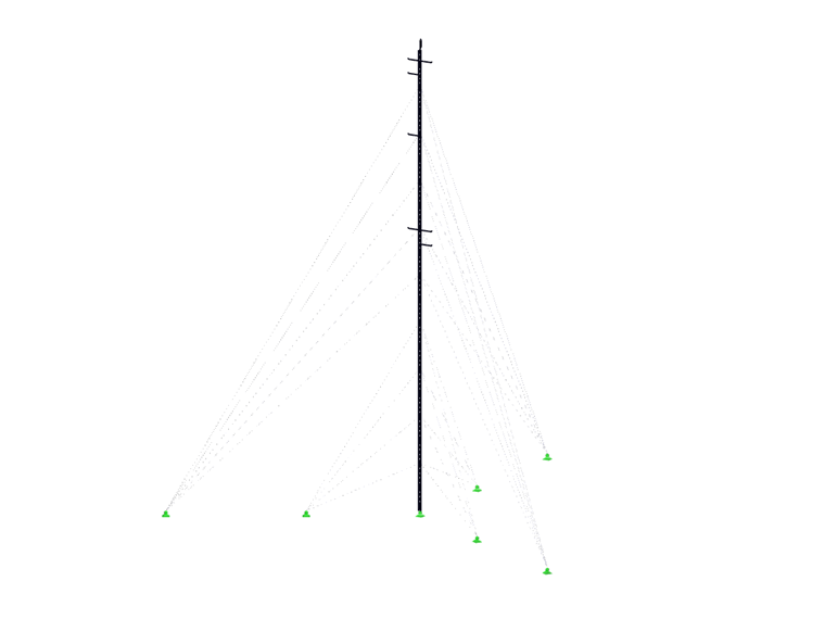
The truss tower with a height of 100 m (328 ft) has a triangular floor plan and consists of tubular steel sections. The center distance between the three main columns is about 60 cm (1 ft). Every 10 m (33 ft), the slender mast is fixed by steel cables. Depending on the load, the cables have a diameter between 12 mm (0.47 in) and 19 mm (0.75 in).
The structure was designed for an average wind speed of vb,0 = 101.71 ft/s (according to the Central Institution for Meteorology and Geodynamics Report [ZAMG]). m3-ZT GmbH generated wind loads utilizing RWIND Simulation and imported them to the RFEM model. The civil engineering office of DI Stallinger Johann+Partner from Upper Austria carried out the verification of the structural analysis and design. This office utilized a different structural analysis and design software and applied the wind loads according to the standard (EN 1991-1-4). One result of the verification was that the support forces from wind in both models only differed by a maximum of 2%.
Industrial climbers and a helicopter helped to assemble the mast. The tower will carry out wind measurements over a period of 1.5 years.
| Location | Windsfeld Flachau / Flachauwinkl Austria |
| Owner | Windsfeld GmbH 5550 Radstadt Austria www.windsfeld.at |
| Structural Design, Assembly Assistance | m3-ZT GmbH 5342 Abersee Austria www.m3-zt.at |


