The CFD simulation (Computational Fluid Dynamics) is a valuable tool for various areas of engineering, design and research. In the following, we present some of the most important advantages of CFD simulations in more detail.
Cost Efficiency
Using CFD simulations in large or complex structural systems is much more cost-effective than performing physical experiments. For example, the digital wind simulation eliminates the costs for the production of prototypes, securing test facilities, and the use of special equipment
Saving Time with CFD Simulations
You can also save some time in the analysis process by using a CFD simulation. The setup and execution are quick and easy, requiring only a few clicks, which saves you a lot of time compared to setting up a physical test. As an engineer, you can thus benefit from iterative analysis processes. Test your designs in a virtual environment to perfect all aspects digitally before deciding on a physical prototype.
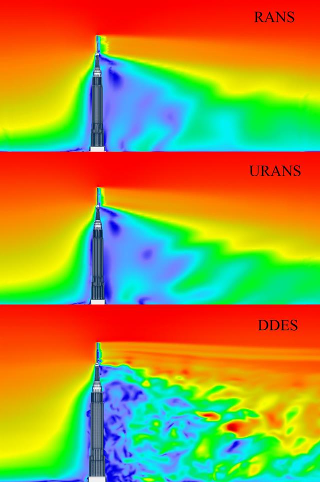
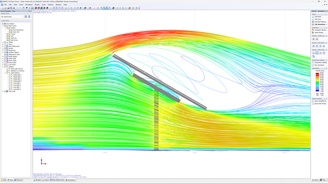
Detailed Visualization
For example, CFD provides you with flow patterns, pressure distributions, and other relevant physical phenomena that would be difficult or impossible to demonstrate experimentally. This additional information gives you an even better insight into the technical data of your project.
Scalability in CFD Simulations
Another advantage of the CFD simulations is the arbitrary scalability without great effort. Do you want to analyze different sizes or configurations of an analysis? In the digital flow tunnel, this is easily possible without any physical changes or new prototypes. A CFD simulation provides you with a wider range of scenarios and analysis parameters.
Sustainability Due to CFD Simulations
Another benefit of the CFD simulation is that it requires fewer physical prototypes and experiments. Lower energy consumption and lower waste production is ideal for achieving sustainability goals, such as reduced material costs and addressing environmental concerns.
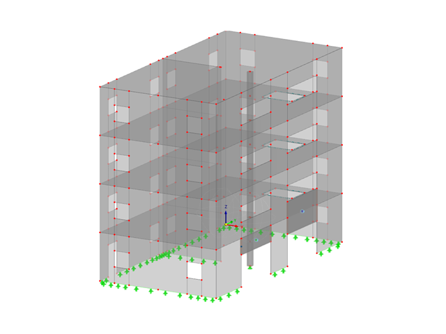
Complexity and Precision
A digital wind tunnel gives you the opportunity to accurately model complex geometries and fluid interactions. This would be difficult to replicate in an experimental setup. The precision of CFD allows you to analyze subtle effects and interactions in a controlled environment. At the same time, the program provides you with complex insights that enhance the comprehension and optimization of structural systems.
The CFD simulations are especially useful if you have a thorough comprehension of the underlying models and assumptions. In most cases, it is best to use a combination of CFD simulations and experimental tests to achieve comprehensive results. This gives you the opportunity to fully understand the behavior of your structures in flow situations.
Are you looking for a way to carry out CFD simulations for your projects? The powerful RWIND is a stand-alone program that allows you to perform flow simulations in various situations. Find more information about the latest program generation here:
RWIND 2
.
Show more