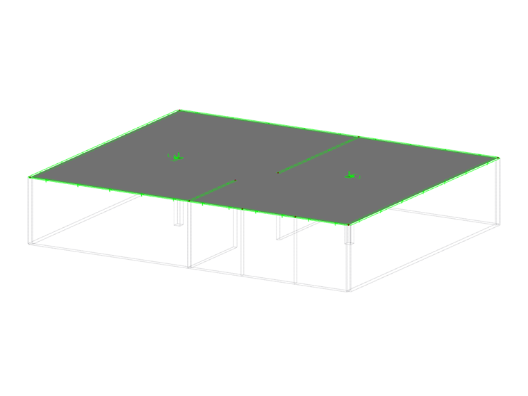
A line support describes the boundary conditions of all FE nodes available along a line. Displacements and rotations on these internal nodes can be prevented or limited by translational and rotational springs.
If you want to assign nonlinear properties to a line support, you can define failure criteria for tensile or compressive forces, tearing and yielding, or work and stiffness diagrams.
The selected box symbol of a user-defined line support indicates the restrained degrees of freedom. The "Hinged" and "Fixed" support types are predefined.
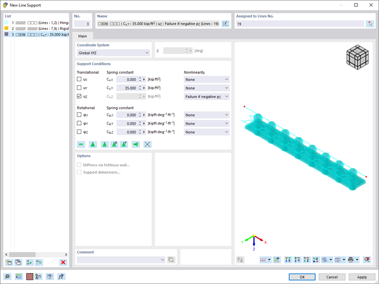
Main
The Main tab manages the basic support parameters.
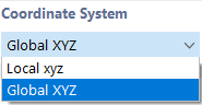
Coordinate System
The properties of the line support can be related as "Global" to the axes X, Y, and Z, or as "Local" to the line axes x, y, z. Indexes in the "Support Conditions" dialog section differ depending on the selection.
You can rotate the axis system of a local line support. A positive angle β effects a right-handed rotation of the support about the positive line axis x.
After the calculation, it is possible to evaluate the support reactions of a rotated line support in relation to both the global and local axis systems.
Support Conditions
The support conditions are divided into "Translational" and "Rotational" degrees of freedom. Translational degrees describe supports in the direction of the support axes; rotational degrees describe restraints about these axes.
To define a support or restraint, select the check box for the respective axis. The check mark indicates that the degree of freedom is blocked and the displacement or rotation of the line in or about the corresponding direction is impossible.
If no support or restraint is available, clear the respective check box. The constant of the translational or rotational spring is then set to zero. You can adjust the "Spring constant" anytime in order to model an elastic support of the line. Enter the spring stiffnesses as design values.
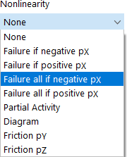
In the "Nonlinearity" column, you can specifically control the transfer of internal forces and moments for each component. Depending on the degree of freedom, suitable entries are available for selection in the list of nonlinearities.
Supports acting nonlinearly are displayed by a different color in the graphic.
Failure if support force/moment is negative or positive
This allows you to control easily whether the support can absorb only positive or negative forces or moments: If a force or a moment acts in the forbidden direction, that particular component of the support fails. The remaining restraints stay effective.
The "negative" or "positive" directions refer to the forces or moments that are applied to the line support with regard to the respective axes (they do not refer to the reaction forces on the part of the support). The signs result from the direction of the global or local axes. For example, if the global Z-axis is oriented downwards, the "Self-weight" load case results in a positive support force pZ.
Failure all if support force/moment is negative or positive
In contrast to the above-mentioned failure of a single component, the support fails completely once the component is ineffective.
When you select a different nonlinearity, you can define the parameters in the Partial Activity, Diagram, or Friction tabs.
Options
The "Stiffness via fictitious wall" check box allows you to determine the stiffness of the support based on the geometry and material data of a wall. Define the parameters in the Stiffness via Fictitious Wall tab.
If the "Concrete Design" add-on is activated, an additional check box is available for defining the support dimensions.
Stiffness via Fictitious Wall
The Stiffness via Fictitious Wall tab is particularly recommended for linear supports of 2D structures. Here, you can determine the support spring constants from the parameters of a wall that is not represented in the model.
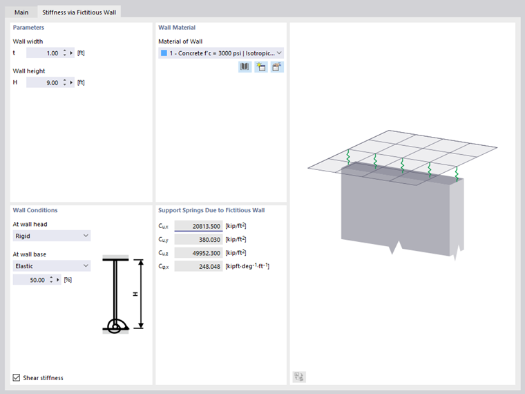
Parameters
Enter the "Wall width" and "Wall height" whose values are required to determine the spring constants.
Wall Material
To determine the spring constants, the material properties of the wall are required. You can select the "Material of Wall" from the list or create a new material using the
![]() and
and
![]() buttons.
buttons.
Wall Conditions
The support type at the wall head and wall base is included in the determination of the translational and rotational springs. The following options are available for selection in the list:
- Pinned
- Elastic
- Rigid
If you select the "Elastic" option, you can specify the degree of restraint at the wall base as a percentage.
The "Shear stiffness" of the wall is taken into account by default when determining the stiffnesses.
Support Springs Due to Fictitious Wall
This dialog section lists the constants of the support springs that result from the geometry and material properties of the wall. The values are transferred to the "Main" tab.
Support Dimensions
The geometry of the support is required to determine the loaded area for the punching shear design. This tab is, therefore, only accessible if the Concrete Design add-on is activated.
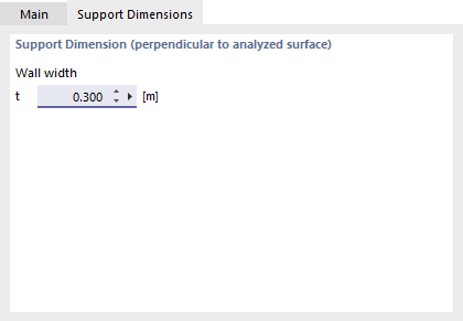
Enter the "Wall width" so that the supported surface can be determined.
Partial Activity
The Partial Activity of a support component is available as a nonlinear property of the support (see the image Selecting Support Nonlinearity).
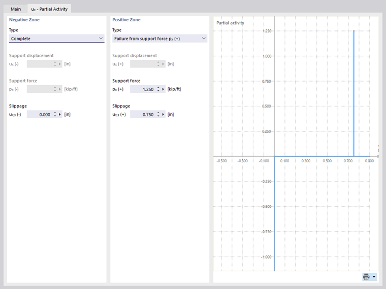
Define the effect of the support for the "Negative Zone" as well as for the "Positive Zone". The sign rules are explained in the section Failure. The "Type" list offers various criteria for the effectiveness of the support.
- Complete: The component of the support is fully effective.
- Fixed from support displacement/support rotation: The stiffness of the translational or rotational spring is effective only up to a certain displacement or rotation. If the limit is exceeded, a fixed support or a restraint becomes effective.
- Tearing from support force/support moment: The support is effective only up to a certain force or moment. If the limit is exceeded, the support fails.
- Yielding from support force/support moment: The support is effective only up to a certain force or moment. If it is exceeded, strains still increase, but not the stresses.
- Failure: The component of the support is not effective.
Most support types can be combined with a "Slippage", which means that the support becomes effective only after a certain displacement or rotation.
Diagram
The Diagram of a support component is available as a nonlinear property of the support (see the image Selecting Support Nonlinearity).
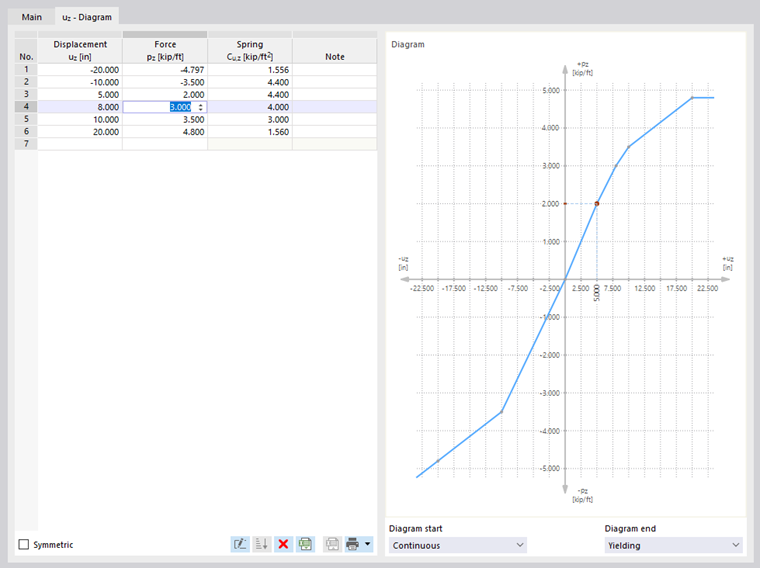
Define the number of definition points for the work diagram by entering the corresponding values in the "Displacement" or "Rotation" column. Then, in the "Force" or "Rotation" column, you can assign the x-coordinates of the displacements or rotations with the support forces or moments.
Use the
![]() button to import the diagram from an Excel spreadsheet. If the order of the definition points is incorrect, you can sort the entries in ascending order with the
button to import the diagram from an Excel spreadsheet. If the order of the definition points is incorrect, you can sort the entries in ascending order with the
![]() button.
button.
The following criteria are available for selection for the "Diagram start" and the "Diagram end":
- Tearing: The support is effective only up to the maximum value of the force or moment. If the limit is exceeded, the support fails.
- Yielding: The support is effective only up to the maximum value of the force or moment. If it is exceeded, strains still increase, but not the stresses.
- Continuous: Beyond the definition range, the spring constant of the last step is applied.
- Stop: The allowable deformation is limited to the maximum value of the displacement or rotation. If the limit is exceeded, a fixed support or a restraint becomes effective.
Friction
The "Nonlinearity" list offers two options to define the Friction of the translational support depending on another support component (see the image Selecting Support Nonlinearity).
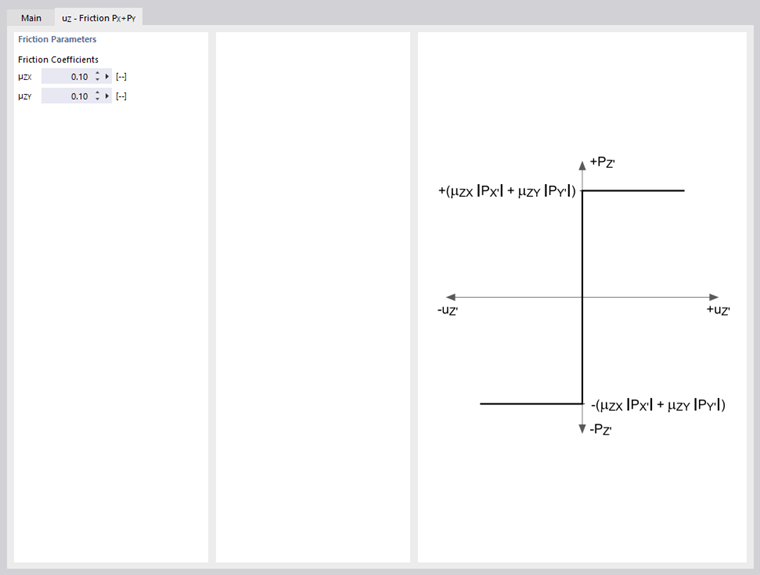
The transferred support forces are related to the axial forces that act in another direction. The following correlation exists between support force and friction force: