


Symbols Used
| L | Beam length |
| b | Beam width |
| h | Beam height |
| E | Modulus of elasticity |
| G | Shear Modulus |
| Iz | Second moment of area about the weak axis |
| IT | Torsion moment of inertia |
| az | Load application distance from the shear center |
Single-Span Beam with Lateral and Torsional Restraint and Without Intermediate Support
| L | 18 | m |
| b | 160 | mm |
| h | 1.400 | mm |
| az | 700 | mm |
| Iz | 477.866.667 | mm4 |
| IT | 1.773.842.967 | mm4 |
| E0.05 | 10.400 | N/mm² |
| G0.05 | 540 | N/mm² |

For the single-span beam with lateral and torsional restraint without intermediate supports shown in Image 01, the equivalent member length results in the case of a load application at the top to:
The factors a1 and a2 can be seen in Image 02 according to the moment distribution.
.png?mw=760&hash=7dfb9668b098804bdded20f2b0205bbc97b03faa)
The critical bending moment can then be calculated as follows:
In this example, we do not increase the product of the 5% quantiles of the stiffness values due to the homogenization of beams made of glued-laminated timber.
Eigenvalue Method for Determining Critical Bending Moment
For more complex systems, it may be advantageous to determine the critical loads, moments, or stresses using the eigenvalue solver. This is directly implemented in the timber design and is controlled via the effective lengths. An elastic material behavior is assumed for a geometric nonlinear behavior. Since the lower quantile value of the critical moment is to be determined, the 5% quantiles should be used for the stiffness parameters E and G. This is done automatically. As a result, the critical load is of importance. This indicates the factor by which the load can be multiplied before the system becomes unstable.
For this example, the beam is loaded with a unit load of 1 kN/m. For this, the bending moment results in:

Next, the lateral and torsional restraints need to be defined. To do this, assign the Effective Length design type to the member and select the Eigenvalue Method type.

By default, the Nodal Supports and Effective Lengths tab defines a lateral and torsional restraint at both the start and end of the member. Therefore, no further settings are required for this example.

The load has a destabilizing effect on the eigenvalue solver by default, meaning it acts on the top of the beam. If this is not the case, the load position for the eigenvalue solver can be changed in the ultimate configuration.

Results from Eigenvalue Analysis
The calculation results in a critical load factor of 9.47 (see the next image).
The critical moment is given by:

If the load is now multiplied by this factor, there will be a deflection of the top chord and the structural system will become unstable. The corresponding mode shape can be displayed graphically in the Results navigator:

The result from the eigenvalue solver agrees very well with the result of the analytical solution.
| Symbol | Value | Unit |
|---|---|---|
| Mcrit,analytical | 375.42 | kNm |
| Mcrit,eigenvalue | 383.72 | kNm |
Single-Span Beam with Lateral and Torsional Restraint and Intermediate Support
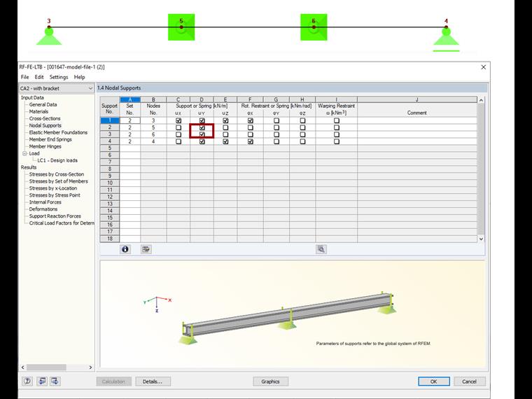
The beam is now supported as rigidly fixed laterally at the third points by a stiffening structure. To do this, two “nodes on member” are assigned to the member, at which the lateral supports act.

Next, the lateral supports are assigned using the effective length:

The location of the lateral support cannot be accounted for using the equations provided in the standard; Therefore, for better comparability, it is assumed to be at the center of shear.
Since the moment distribution is nearly constant in the middle section, a constant moment distribution is assumed for the warping length factors as a good approximation.

The value a1 is thus 1.0 and a2 is 0. This results in an effective length of L = 6.0 m to
and the critical moment to
The eigenvalue solver results in a critical load factor of 27.64, taking into account the intermediate supports at the shear center.
The following applies for the critical moment:

The analytical approximation is also very good in this case.
| Symbol | Value | Unit |
|---|---|---|
| Mcrit,analytical | 1142.41 | kNm |
| Mcrit,eigenvalue | 1119.46 | kNm |
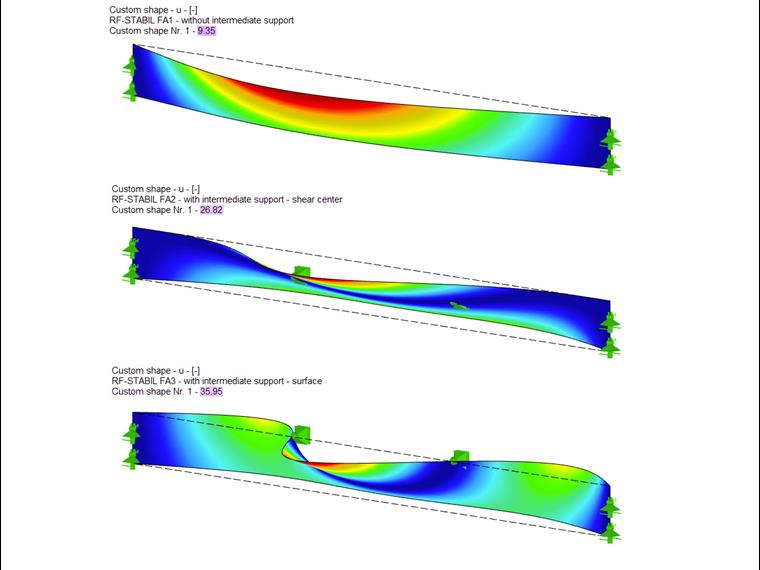
If the intermediate support acts on the upper side (see the next image), the critical load factor becomes larger (32.5325), because this position has a more favorable effect on the lateral buckling behavior of the beam.

The analytical approximation is also relatively good for this case.
Alternative Analysis on Surface Model
You can also use RFEM and the Structure Stability add-on to calculate the critical load factors. For this, it is necessary that you model the beam as an orthotropic surface. The results from add-on correspond very well to the member calculation. The first mode shape and the corresponding critical load factor are shown in the next image.

| System | Mcrit,analytical | Mcrit,eigenvalue | Mcrit,surface |
|---|---|---|---|
| Without intermediate support | 375.42 kNm | 383.72 kNm | 377.43 kNm |
| With intermediate support in shear center | 1,142.41 kNm | 1,119.46 kNm | 1,079.28 kNm |
| With intermediate support on top chord | - | 1,488.05 kNm | 1,447.20 kNm |
In most cases, it is probably sufficient to determine the critical bending moment Mcrit or the critical bending stress σcrit using the analytical equations from the literature. For special cases, two options for implementation using RFEM and RSTAB were shown. While the "Timber Design" add-on is used to perform the calculation using members, the Structure Stability add-on allows you to perform even more complex stability design checks. One example is a lateral and torsional restraint that is not arranged over the entire beam height. This can be analyzed easily with a surface model.