RFEM distinguishes between \(M_{t,pri}\) (primary St. Venant torsional moment) and \(M_{t,sec}\) (secondary torsional moment). \(M_{t,sec}\) combines two physically distinct components: the torsional moment resulting from the warping torsion \(M_{t,sec,\omega}\) and the component induced by the axial force \(M_{t,sec,N}\). Both components of \(M_{t,sec}\) are taken into account only if the Torsional Warping add-on (7 DOF) has been activated.
$$\Sigma M_x = M_{t,pri} + \underbrace{M_{t,sec,\omega} + M_{t,sec,N}}_{M_{t,sec}} \qquad (1)$$
Here, \(\Sigma M_x\) is the total torsional moment about the member’s longitudinal axis x.
\(M_{t,pri}\): Primary Torsional Moment
$$M_{t,pri} = G\,I_T\,\vartheta^{\prime} \qquad (2)$$
where
- \(G\) is the shear modulus,
- \(I_T\) is the torsional moment of inertia (St. Venant’s torsional resistance),
- \(\vartheta^{\prime}\) is the warping, that is, the derivative of the rotation \(\vartheta\) with respect to the longitudinal axis x of the member. In the following, prime symbols always denote derivatives with respect to x.
\(M_{t,pri}\) is the component of the torsional moment that the cross-section resists solely through its warping \(\vartheta^{\prime}\) (rotation per unit length). It is proportional to the warping; the proportionality factor is the torsional stiffness \(G\,I_T\).
\(M_{t,pri}\) appears in every calculation, including those based on the linear static analysis. For non-warped cross-sections (warping resistance \(I_\omega = 0\)), no warping bimoment \(M_\omega\) arises and, consequently, no warping torsion. In the absence of an axial force, \(M_{t,pri}\) is then the only torsional moment.
\(M_{t,sec}\): Secondary Torsional Moment
Component 1: Warping Torsion \(M_{t,sec,\omega}\)
$$M_\omega = -E\,I_\omega\,\vartheta^{\prime\prime} \qquad M_{t,sec,\omega} = M_\omega^{\prime} = -E\,I_\omega\,\vartheta^{\prime\prime\prime} \qquad (3\text{a,b})$$
where
- \(M_\omega\) is the warping bimoment,
- \(E\) is the modulus of elasticity,
- \(I_\omega\) is the warping resistance (warping constant of 2nd degree).
\(M_{t,sec,\omega}\) is the torsional moment resulting from the restraint against warping, which is the derivative of the warping bimoment \(M_\omega\).
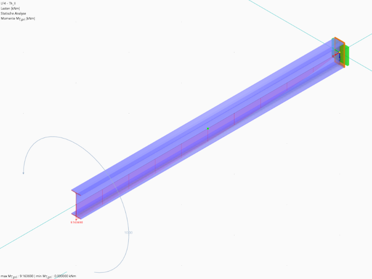
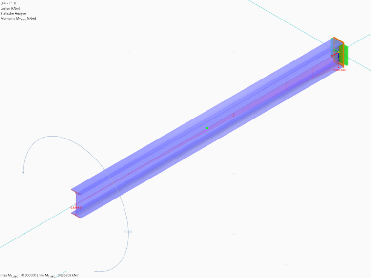
As an example, there is a section that is restrained on one side, which is the I-section. A torsional moment of 10 kNm acts at the free end. There is no axial force, so the component \(M_{t,sec,N}\) is omitted, and \(M_{t,sec}\) corresponds here solely to the warping torsion \(M_{t,sec,\omega}\).
The distributions show how the torsional force is distributed along the members between the two support mechanisms:
- At the restraint, the cross-section cannot warp. Therefore, (\(\vartheta^{\prime} = 0\)) and \(M_{t,pri} = G\,I_T\,\vartheta^{\prime}\) reduces to 0. The entire torsional moment is carried by warping torsion: \(M_{t,sec} = 10\) kN·m. Mechanically, the two flanges bend in opposite directions within their own planar configuration (laterally, about the z-axis of the cross-sections). The shear forces in the two flanges are directed oppositely and form a force couple. The lever arm is the distance between the flange centerlines. This force couple balances the torsional moment. This is also where the warping bimoment reaches its maximum (\(M_\omega = 15{,}70\) kNm²).
- As the distance from the restraint increases, the warping restraint decreases. The cross-section can warp more and more, and St. Venant torsion takes over the majority of the load.
- At the free end, the cross-section can warp freely; therefore, the warping bimoment is \(M_\omega = 0\). Nevertheless, \(M_{t,sec}\) is not zero there, but rather 0.84 kN·m.
The reason: In this example, no axial force acts; therefore, \(M_{t,sec}\) consists solely of the warping torsion \(M_{t,sec,\omega}\). This component corresponds to the derivative of the warping bimoment along the member axis and not to the value of \(M_\omega\) itself. Although \(M_\omega\) is zero at the free end, it is still changing there, so \(M_{t,sec}\) is not zero. The beam is too short for the warping torsion to decrease completely by the time it reaches the free end.
At every point along the beam, the equilibrium condition \(M_{t,pri} + M_{t,sec} = 10\) kNm applies; at the free end, for example, \(9{,}16 + 0{,}84 = 10{,}00\) kNm.
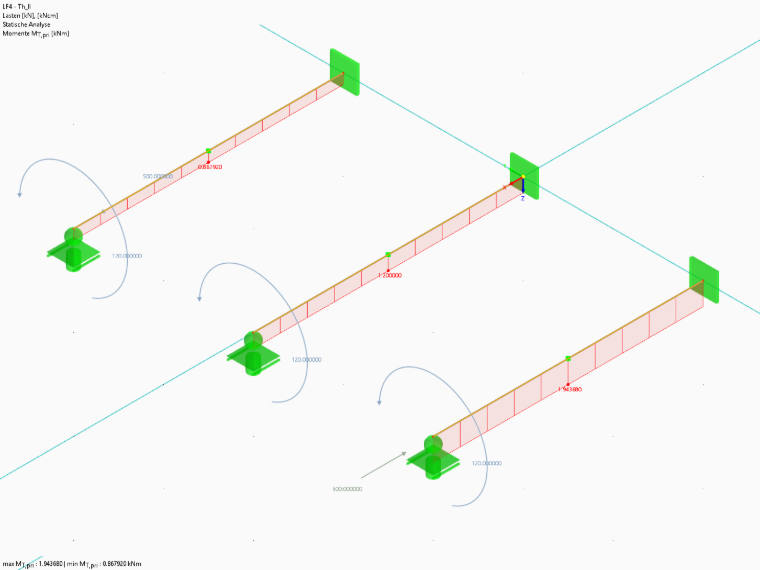
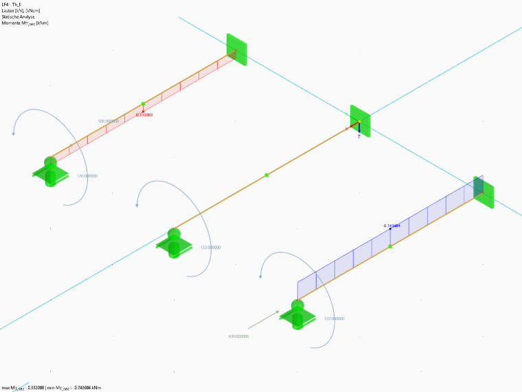
The following images show the distributions. The “Mt_sec_omega” model, which can be used to check the results, is included in the appendix.
Component 2: Torsional Moment Induced by Axial Force \(M_{t,sec,N}\)
If an axial force acts on a twisted member, an additional torsional moment component \(M_{t,sec,N}\) arises. It is only taken into account in the second-order analysis, provided that the “Torsional Warping” add-on is activated:
$$M_{t,sec,N} = N\,i_M^2\,\vartheta^{\prime} \qquad (4) \qquad \text{(N is positive as a tensile force)}$$
where
- \(N\) is the axial force,
- \(i_M\) is the polar radius of gyration related to the shear center, where \(i_M^2 = i_p^2 + y_M^2 + z_M^2\),
- \(i_p\) is the polar radius of gyration related to the center of mass, where \(i_p^2 = (I_y + I_z)/A\),
- \(y_M\), \(z_M\) are the coordinates of the shear center with respect to the center of mass,
- \(I_y\), \(I_z\), \(A\) are the moments of inertia and cross-sectional area.
For doubly symmetric cross-sections, the shear center and the center of mass coincide; in this case, \(i_M^2 = i_p^2\) applies.
A tensile force has a stiffening effect and reduces warping, while a compressive force increases it. This effect corresponds to compression bending, in which the deflection increases disproportionately as the compressive force increases. The ratio \(N\,i_M^2\) to \(G\,I_T\) is decisive. For open cross-sections, \(G\,I_T\) is small; therefore, depending on the load, neglecting \(M_{t,sec,N}\) quickly becomes unacceptable. Since axial force and torsion frequently occur together in spatial structures, this is relevant in practice. In closed cross-sections, on the other hand, \(G\,I_T\) is so large that \(M_{t,sec,N}\) can be neglected in many cases.
Note on interpreting the results: A compressive force amplifies the torsion. Due to warping, the longitudinal fibers become inclined, and the compressive force causes an additional torsional moment in the direction of rotation within these fibers. Therefore, the St. Venant torsion has to counteract more than the applied torsional moment; \(M_{t,pri}\) becomes greater than the external torsional moment. Since the equilibrium \(M_{t,pri} + M_{t,sec} =\) external torsional moment also applies with an axial force, this effect appears in the results as a negative component \(M_{t,sec,N}\). In the case of tension, the opposite is true: \(M_{t,sec,N}\) is positive, the tensile force contributes part of the torsional moment, and \(M_{t,pri}\) becomes smaller.
The following images show this effect. It can also be reproduced in the attached file “Mt_sec_N.”
‘’‘Models to Download’‘’
Both models used in this post can be downloaded here for your reference: