130 Results
View Results:
Sort by:

Structures are naturally three-dimensional. However, because it was impossible to perform calculations on three-dimensional models easily in the past, the structures were simplified and broken down into planar subsystems. With the increasing performance of computers and related software, it is often possible to do without these simplifications. Digital trends such as Building Information Modeling (BIM) and new options for creating realistic visualized models reinforce this trend. But do 3D models really offer an advantage, or are we just following a trend? The following text presents some arguments for working in 3D models.
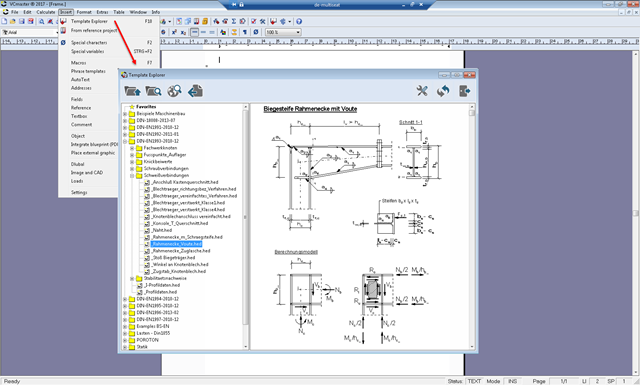
An interface can be used to export the RFEM/RSTAB printout report to VCmaster and continue editing there. VCmaster is a word processing program for engineers.
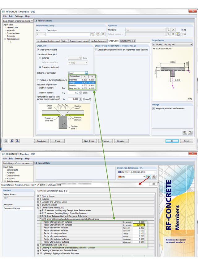
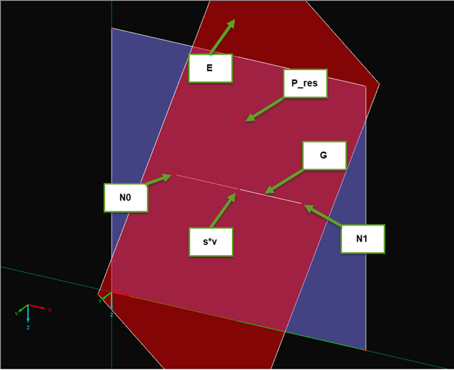
The shear resistance design value of a joint depends mainly on the formation or the roughness of the connection. When determining the ultimate limit state, this is considered by the factors µ (friction) and c (adhesion percentage of the contact area of the composite concrete).
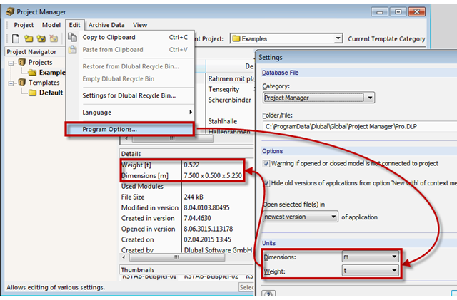
The network-capable Project Manager controls the projects of all Dlubal Software applications in one central location. A table displays the important information for each model and corresponding file. Now, you can set dimension and weight units in the program options.

Our webservice offers users the opportunity to communicate with RFEM 6 and RSTAB 9 using various programming languages. Dlubal's high-level functions (HLFs) allow you to expand and simplify the WebService's functionality. In line with RFEM 6 and RSTAB 9, using our WebService makes the engineer's work easier and faster. Check it out now! This tutorial shows you how to use the C# library by means of a simple example.

General thin-walled cross-sections often have asymmetrical geometries. The principal axes of such sections are then not parallel to the horizontally and vertically aligned axes Y and Z. When determining the cross-section properties, the angle α between the center-of-gravity axis y and the principal axis u is determined in addition to the principal axis-related moments of inertia.

The data exchange between RFEM 6 and Allplan can be done using various file formats. This article describes the data exchange of a determined surface reinforcement using the ASF interface. This allows you to display the RFEM reinforcement values as level curves or colored reinforcement images in Allplan.

By means of result combinations, it is possible to create, among other things, the envelopes for internal forces and deformations. Thus, you can quickly find the maxima and minima for the subsequent design.

Wind direction plays a crucial role in shaping the outcomes of Computational Fluid Dynamics (CFD) simulations and the structural design of buildings and infrastructures. It is a determining factor in assessing how wind forces interact with structures, influencing the distribution of wind pressures, and consequently, the structural responses. Understanding the impact of wind direction is essential for developing designs that can withstand varying wind forces, ensuring the safety and durability of structures. Simplified, the wind direction helps in fine-tuning CFD simulations and guiding structural design principles for optimal performance and resilience against wind-induced effects.
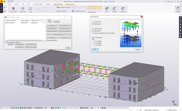
The Master's Thesis of Tamás Drávai, Haroon Khalyar, and Gábor Nagy deals with the effect of interoperability between Computer Aided Design (CAD) and Finite Element Modeling (FEM) software on structural modeling and analysis. Several case studies were conducted, where a building information model was transferred from CAD to FEM software with different data exchange formats.
Building Information Modeling is making headlines in building design. While some engineers only use BIM methods for planning, others are dealing with this topic for the first time or rarely have time for it in their daily working routine. However, one topic seems the most important in structural engineering: How can structural engineers benefit from BIM?

The response spectrum analysis is one of the most frequently used design methods in the case of earthquakes. This method has many advantages. The most important is the simplification: It simplifies the complexity of an earthquake to such an extent that an analysis can be carried out with reasonable effort. The disadvantage of this method is that a lot of information is lost due to this simplification. One way to mitigate this disadvantage is to use the equivalent linear combination when combining the modal responses. This article explains this option by describing an example.

The response spectrum analysis is one of the most frequently used design methods in the case of earthquakes. This method has many advantages. The most important is the simplification: It simplifies the complexity of earthquakes so far that the design can be performed with reasonable effort. The disadvantage of this method is that a lot of information is lost due to this simplification. One way to moderate this disadvantage is to use the equivalent linear combination when combining the modal responses. This article explains this option by describing an example.
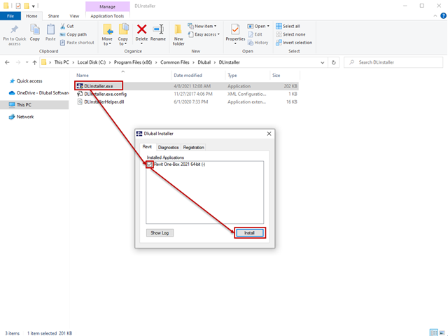
The interface to Autodesk Revit is installed automatically during the installation of RFEM 5 or RSTAB 8. Subsequent installation of the plug‑in is possible through the execution of Revit-Installer.exe.
Buildings must be designed and dimensioned in the way that both vertical and horizontal loads are conducted safely and without large deformations in the building. Examples of horizontal loads are wind, unintentional inclination, earthquake, and a blast.
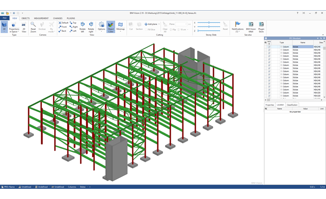
In RFEM, structures can be modeled and analyzed in a spatial environment. The permanent 3D visualization helps you to better understand complex models and to represent the force flux. However, you can switch from a spatial mode to a planar sheet mode in the documentation of a calculation. To do this, you have to describe the spatial calculation of the structure with all the necessary properties on "flat" paper pages for an independent reader. Usually, you try to display the load actions and the corresponding results by using an orthogonal view of the substructure of the entire structure. Obviously, the load symbols depicted in the 3D mode in a view perpendicular to the load become unrecognizable due the missing expansion. In order to still be able to create a clear representation of all information, the corresponding adjustments are available in RFEM.
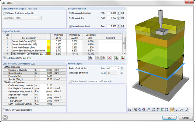
As of program version x.06.1103, you can enter a soil profile in RF‑/FOUNDATION Pro. This gives you the advantage of setting several soil layers with different soil parameters above and below the foundation base. To enter the soil layers, there is a library with various soil types that can also be extended with user‑defined soils. The user-defined soil profile is shown in an interactive information graphic. Any change (for example, a soil thickness modification) is reflected in the graphic immediately.
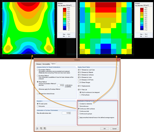
Just as in the RFEM Display Navigator, you can set the distribution of internal forces in surfaces in RF‑STEEL Surfaces. Since deformations are always the result of the FEM calculation, the corresponding forces will be recalculated. This means that the internal forces on an FEM element are calculated depending on the composition (triangular or square) in three or four places. In order to obtain continuous internal forces and thus a smoothed distribution, these internal forces have to be interpolated. Interpolation is done by selecting the "Distribution of internal forces" option in the surfaces.

In the RF-/TIMBER Pro, RF-/TIMBER AWC, and RF-/TIMBER CSA add-on modules, you can consider the resulting deformation of a member or set of members. In addition to the local directions y and z, you have the option "R." This allows you to compare the total deflection of a girder to the limit values given in the standards.

In the age of BIM, data exchange between the various disciplines of structural engineering is becoming increasingly important. Since each software has its own specifications with regard to the description of cross-sections and materials, RFEM and RSTAB offer a conversion table (mapping file).
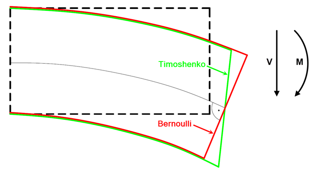
In current literature, the formulas used to determine internal forces and deformations manually are usually specified without considering the shear deformation. The deformations resulting from shear force are often underestimated in timber construction in particular.
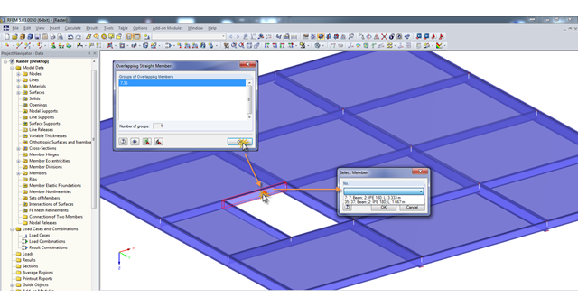
A modell check allows you to find overlapping members, among other things. However, this targeted selection could cause some minor problems. Therefore, there is a selection window now available, which appears when you click on one of the elements. This appears by clicking on one of the elements. Additional information helps you to select the correct member.
If you read out the results of a surface by means of the COM interface, you get a one-dimensional field with all results at the FE nodes or grid points. To get the results on the edge of a surface or along a line within the surfaces, you have to filter out the results in the area of the line. The following article describes a function for this step.
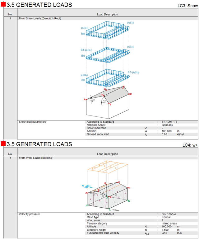
In addition to the general information about the generated snow and wind loads in the form of tables, the corresponding schematic sketches are also available in the printout report of RFEM and RSTAB now. These are displayed separately for each load case.
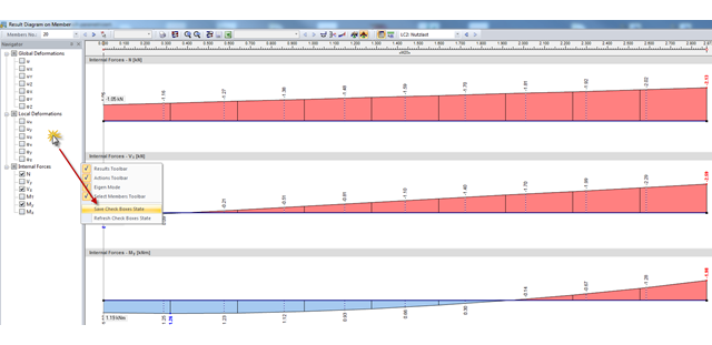
In RFEM and RSTAB, the check boxes for deformation in result diagrams are selected by default. To avoid creating a new user-defined result display every time, you can save the selection of check boxes displayed on the left.

In RFEM 5 and RSTAB 8, it is possible to assign nonlinearities to member hinges. In addition to the nonlinearities "Fixed if" and "Partial activity", you can select "Diagram". If you select the "Diagram" option, you have to specify the according settings for the activity of the member hinge. For the individual definition points, it is necessary to specify the abscissa and ordinate values (deformations or rotations and the according internal forces) that define the hinge.
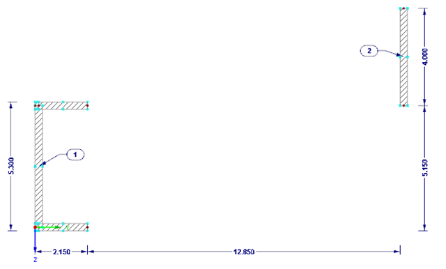
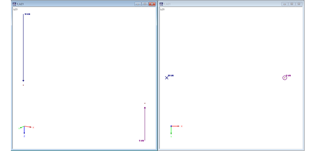
![System and Loading According to [1]](/en/webimage/009634/2419765/01-en-png-png.png?mw=640&hash=5e657e3feb5c1bb6d21727468dd85d91e1c9f29f)
A structural analysis does not only determine and design internal forces and deformations. It also ensures that the forces and moments in a structure are generated in a reliable way and applied to the foundation. Dlubal Software provides a wide range of products for the structural analysis and design of steel and timber connections. The RF-/JOINTS Steel – Column Base add-on module allows you to design footings of hinged and restrained column bases. The design can be performed for column base plates with or without stiffeners.

If a rib is part of a nonlinear design or is rigidly connected to following walls, a surface should be used for the modeling instead of a member. So that the rib can still be designed as a member, a result member with the correct eccentricity is required, which transforms the surface internal forces into member internal forces.
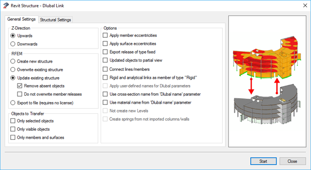
BIM is often used when it comes to data management in civil engineering. The individual disciplines of architecture, structural design, construction, and structural monitoring are coming closer together. Building Information Modeling makes this possible.. Dlubal Software provides a wide range of formats for data exchange. The following article explains the details of the interface with Autodesk Revit and, in particular, the export settings.

In RFEM 6, the results for the FE mesh nodes are determined using the finite element method. For the distribution of internal forces, deformations, and stresses to be continuous, these nodal values are smoothed through an interpolation process. This article will introduce and compare the different types of smoothing that you can use for this purpose.