23 Results
View Results:
Sort by:
In the global selection of the printout report, you can select in the lower "Display" section whether you want to create a table of contents. The table of contents of the printout report usually requires too much space when displayed in one column.
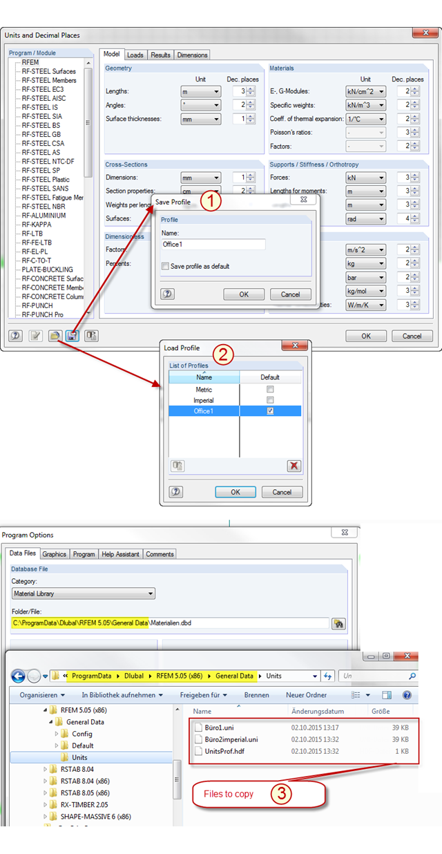
In RFEM and RSTAB, there are two predefined unit profiles available by default. These profiles cover the metric and the imperial systems of measurement. You can individually adjust the units predefined by Dlubal Software, including the decimal places used. To avoid losing the changes you have made, you can save a new profile for the units (see Item [1] in the picture). The stored profile can be loaded again (see Item [2] in the picture) or transferred from PC to PC. To do this, simply copy the content of the "Units" folder in the RFEM or RSTAB file directory from one PC to another (see Item [3] in the picture). In this way, you can achieve an office standard regarding the units used in all your workplaces.
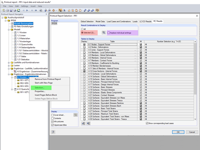
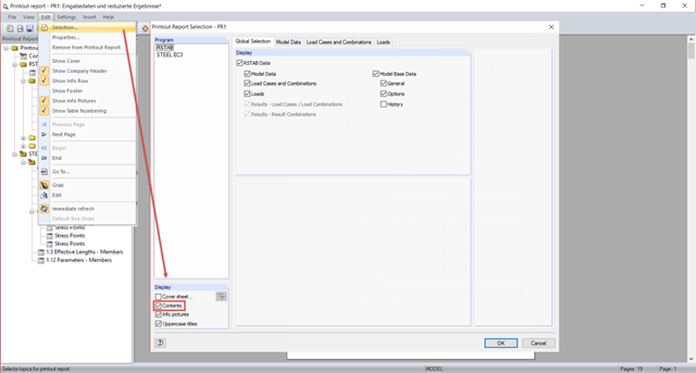
The content to be displayed in the loading and result tables can be managed in the global selection of the printout report (red).
If a bending load of a brittle beam element (an unreinforced concrete beam) is increased by means of the bending capacity, the structure responds by breaking the cross-section and the member is separated into two segments. At the time of the failure, the broken part suddenly loses its potential to transfer the bending moment. Due to the segmentation, the critical part also fails to transfer the other force types, such as axial forces.
You can change the content and appearance of a toolbar under "View" → "Arrange Toolbars Customized". This way, you can easily arrange and save frequently used commands in specific user‑defined toolbars. In addition to the default arrangement on the top of the screen, you can dock the toolbars on the left and right edges of the screen for a better overview.
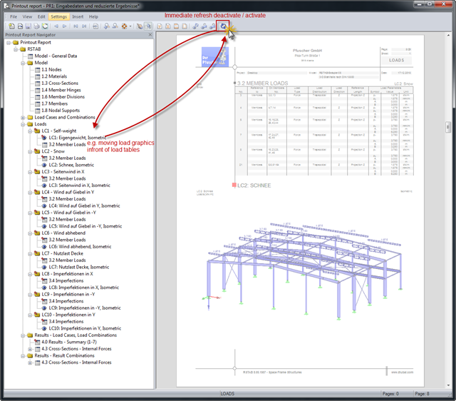
Input data and results can be clearly arranged in a printout report. The contents are listed in compliance with the program-specific definition. If the order of the contents does not correspond to your requirements, you can move the individual parts anywhere in the printout report.
Due to the special properties of glass, you also have to pay close attention to the details when modeling in an FE model. Glass has a very high compressive strength and is, therefore, generally only designed for its tensile stresses. One particular disadvantage of the material is its brittleness. Stress peaks that occur in the calculation must, therefore, not be readily neglected.
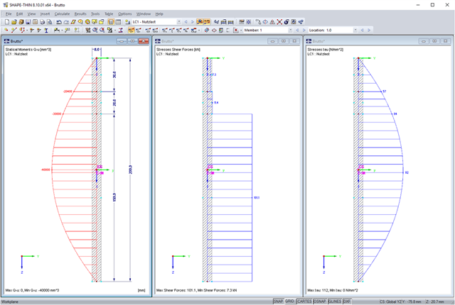
SHAPE-THIN allows you to calculate section properties and stresses of any cross-sections. If a flange or a web is weakened by bolt holes, you can consider this by using null elements. The stresses are subsequently recalculated with the reduced cross-section values. In this case, it is necessary to pay a special attention to shear stresses. By default, these are set to zero in the area of the null elements. When recalculating shear stresses with the reduced cross-section values and without further adaptation, it turns out that the integral of the shear stresses is no longer equal to the applied shear force. The following example shows in detail how to calculate the shear stress.
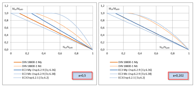
RF-/STEEL EC3 allows you to perform plastic design checks of cross‑sections according to EN 1993‑1‑1, Sec. 6.2. You should pay attention to the interaction of loading due to the bending and axial force for I‑sections, which is regulated in Sec. 6.2.9.1.

In the case of wall-like load-bearing behavior of the cross-laminated timber plate, special attention must be paid to the shear deformation in the plane of the pane and thus, in particular, to the displaceability of the fasteners.

The support of the cross-laminated timber panel deserves special attention. Usually, a cross‑laminated wall is secured against shearing by means of shear connectors and against lifting forces by means of tie rods.
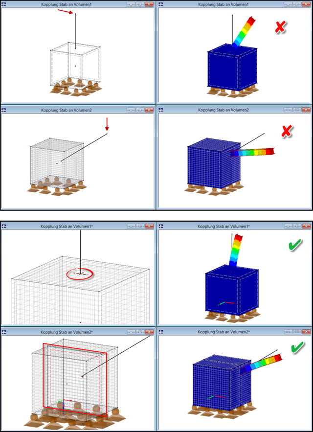
If a slender component (member) is to be connected to a massive component (solid), it is necessary to pay attention to the correct connection of both elements.

For the stability design of members and sets of members with a uniform cross-section, you can use the equivalent member method according to EN 1993-1-1, 6.3.1 to 6.3.3. However, as soon as a tapered cross-section is available, this method can no longer be used, or only used to a limited extent. The RF-/STEEL EC3 add-on module can automatically recognize these cases and switch to the general method.
Buildings must be designed and dimensioned in the way that both vertical and horizontal loads are conducted safely and without large deformations in the building. Examples of horizontal loads are wind, unintentional inclination, earthquake, and a blast.

The response spectrum analysis is one of the most frequently used design methods in the case of earthquakes. This method has many advantages. The most important is the simplification: It simplifies the complexity of an earthquake to such an extent that an analysis can be carried out with reasonable effort. The disadvantage of this method is that a lot of information is lost due to this simplification. One way to mitigate this disadvantage is to use the equivalent linear combination when combining the modal responses. This article explains this option by describing an example.

When designing steel columns or steel beams, it is usually necessary to carry out cross-section design and stability analysis. While the cross-section design can usually be performed without giving further details, the stability analysis requires further user-defined entries. To a certain extent, the member is cut out of the structure; therefore, the support conditions have to be specified. This is particularly important when determining the ideal elastic critical moment Mcr. Furthermore, it is necessary to define the correct effective lengths Lcr. These are required for the internal calculation of slenderness ratios.

Blast loads from high-energy explosives, either accidental or intentional, are rare but may be a structural design requirement. These dynamic loads differ from standard static loads due to their large magnitude and very short duration. A blast scenario can be carried out directly in an FEA program as a time history analysis to minimize loss of life and evaluate varying levels of structural damage.

According to Book 631 of the DAfStb (German Committee for Structural Concrete), Chapter 2.4, the structural behavior of ceilings changes if their continuous support by walls is interrupted in areas of openings. Depending on the length of the opening area and the plate thickness, measures are necessary regarding the analysis of the ceiling in the area of the opening.

Before creating a structural model, every user gives thought to the boundary parameters of the system and how best to represent the model. Special attention should be paid to the orientation of the global coordinate system. In engineering, the global Z‑axis is usually oriented downwards (in the direction of the dead load), while it tends to be upwards in architecture. These differences can often lead to complications during modeling; for example, when you replace global models or DXF layers.
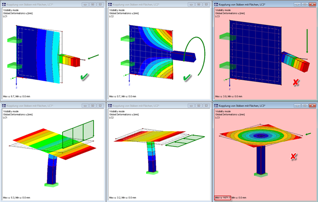
Pay particular attention to the connection points of members and surfaces when you deal with mixed systems, because not all internal forces can always be transferred without difficulty at the coupling location.