181 Results
View Results:
Sort by:

If a canopy roof (for example, a filling station roof) should be designed, a load determination with regard to Section 7.3 of EN 1991-1-4 is required. This article shows the design of a slightly inclined troughed roof, with an example.

Using RF-CONCRETE Members, concrete column design is possible according to ACI 318-14. Accurately designing concrete column shear and longitudinal reinforcement is important for safety considerations. The following article will confirm the reinforcement design in RF-CONCRETE Members using step-by-step analytical equations as per the ACI 318-14 standard, including required longitudinal steel reinforcement, gross cross-sectional area, and tie size/spacing.
Downstand beams or T-beams are often used in reinforced concrete structures. In contrast to the previous representation and calculation options where, for example, a downstand beam was considered as a fixed support and the determined support reaction was applied to a separate member structure using a T-beam section, the ultimate structural FEA software like RFEM allow you to consider the structure as a whole and thus achieve a more precise analysis.

Cross-section properties in RFEM and RSTAB include different types of shear areas. This technical article explains the calculation and meaning of various values.
![Time-Dependent Settlement Components [2]](/en/webimage/009673/2419908/01-en-png-png.png?mw=640&hash=5e657e3feb5c1bb6d21727468dd85d91e1c9f29f)
For the serviceability limit state design according to Section 6.6 of Eurocode EN 1997‑1, settlement has to be calculated for spread foundations. RF-/FOUNDATION Pro allows you to perform the settlement calculation for a single foundation. For this, you can chose between an elastic and a solid foundation. By defining a soil profile, it is possible to consider several soil layers under the foundation base. The results of the settlement, foundation tilting, and vertical soil contact stress distribution are displayed graphically and in tables to provide a quick and clear overview of the calculation performed. In addition to the design of the foundation settlement in RF-/FOUNDATION Pro, the structural analysis determines the representative spring constants for the support and can be exported to the structural model of RFEM or RSTAB.

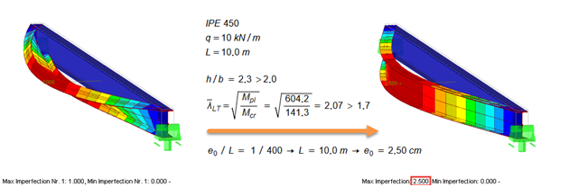
This example is described in technical literature [1] as Example 9.5 and in [2] as Example 8.5. A lateral-torsional buckling analysis must be performed for a principal beam. This beam is a uniform structural member. Therefore, the stability analysis can be carried out according to Clause 6.3.3 of DIN EN 1993-1-1. Due to the uniaxial bending, it would also be possible to perform the design using the General Method according to Clause 6.3.4. Additionally, the determination of the moment Mcr is validated with an idealized member model in line with the method mentioned above, using an FEM model.
There are different options to model composite cross‑sections in RFEM. In the following example, three different modeling options for a composite cross‑section, consisting of a rolled steel section HEA 300 and a rectangular cross‑section made of concrete w/l = 100/30 cm will be displayed and explained.
![Parameters of Effective Slab Width (Figure 5.3 [1])](/en/webimage/009561/2419376/01-en-png.png?mw=640&hash=c76563b459152b19c98197ea6ba342be89d9a5bc)
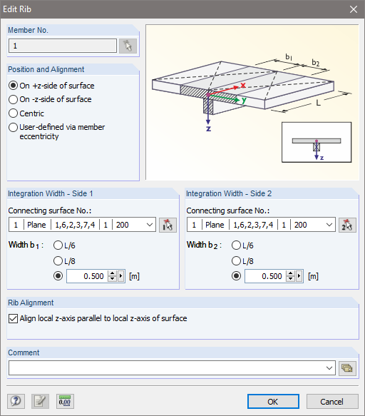
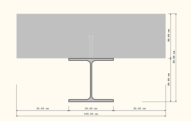
In the case of combined FEM structures (surface and member elements) as well as folded plate structures, it is possible to attribute a beam structure for the design on a member to a fictitious T-beam cross-section, whose geometry depends on the effective width. When using the "Rib" member type in RFEM, the stiffness is represented by a slab component (surface element) and a web component (member element). This approach has some design specifics that are explained in this article.
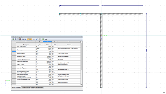
The design of cross-sections usually requires many different cross-section properties. In RFEM and RSTAB, all required properties of standardized cross-sections are available in the cross-section library and can be used directly for the calculation. If the cross-sections are not standardized, SHAPE-THIN allows you to use these cross-sections, too. You can simply enter the geometry to determine all required cross-section properties. The following example shows the calculation of a shear area on a practical example.

The RF-/STEEL EC3 add‑on module performs a detailed cross‑section classification on each design before the design is carried out. Thus, the susceptibility to local buckling of all cross-section parts is evaluated. The defined cross-section class has an effect on the resistance and rotational capacity determination.

The classification of cross-sections is intended to determine the limits of resistance and rotational capacity due to local buckling of cross-section parts. In EN 1999‑1‑1, 6.1.4.2 (1), four classes are defined.
According to EN 1993‑1‑1 [1], it is necessary to use the equivalent geometric imperfections with values that reflect the possible effects of all types of imperfections. EN 1993‑1‑1, Section 5.3, specifies basic imperfections for the global analysis of frames as well as member imperfections.
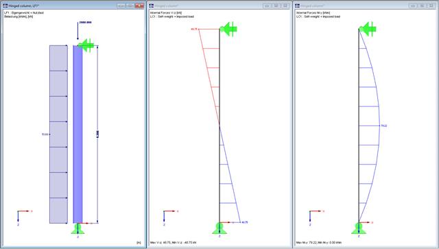
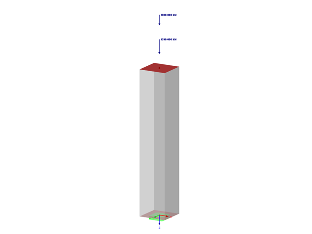
In this technical article, a hinged column with a centrally acting axial force and a linear load that acts on the major axis are designed according to EN 1993-1-1 with the aid of the RF-/STEEL EC3 add-on module. The column head and column base are assumed as a lateral and torsional restraint. The column is not held against rotation between the supports. The cross-section of the column is an HEB 360 from S235.

Utilize the RF-/STEEL Cold-Formed Sections module extension to perform ultimate limit state designs of cold-formed sections according to EN 1993-1-3 and EN 1993-1-5. In addition to the cold-formed cross-sections from the cross-section database, you can design general cross-sections from SHAPE-THIN.

The following article describes the design of a single-span beam subjected to bending and compression, which is performed according to EN 1993‑1‑1 in the RF-/STEEL EC3 add-on module. Since the beam is modeled with a tapered cross-section and thus it is not a uniform structural component, the design must be performed either according to General Method in compliance with Sect. 6.3.4 of EN 1993‑1‑1, or according to the second-order analysis. Both options will be explained and compared, and for the calculation according to the second-order analysis, there is an additional design format using Partial Internal Forces Method (PIFM) available. Therefore, the design is divided into three steps: design according to Sect. 6.3.4 of EN 1993‑1‑1 (General Method), design according to the second‑order analysis, elastic (warping torsion analysis), design according to the second‑order analysis, plastic (warping torsion analysis and Partial Internal Forces Method).

Using the Concrete Design add-on, concrete column design is possible according to ACI 318-19. The following article will confirm the reinforcement design of the Concrete Design add-on using step-by-step analytical equations as per the ACI 318-19 standard, including the required longitudinal steel reinforcement, gross cross-sectional area, and tie size/spacing.
This article deals with rectilinear elements of which the cross-section is subjected to axial compressive force. The purpose of this article is to show how very many parameters defined in the Eurocodes for concrete column calculation are considered in the RFEM 5 structural analysis software.

Closed circular cross-sections are ideal for welded truss structures. The architecture of such constructions is popular when designing transparent roofs. This article shows the special features of the connection design using hollow sections.

This article deals with elements concerning which the cross-section is subjected simultaneously to a bending moment, a shear force, and an axial compressive or tensile force. However, in our example we will not include loading due to shear force.
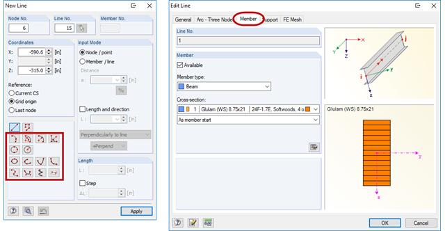
RFEM offers the possibility to model also curved beams. To do this, a curved line must be created first (see Figure 01). This line can then be assigned a beam with a cross-section. The advantages over modeling with beam segments are easier handling during the modeling, as well as a clearer result output of the internal forces.