27 Results
View Results:
Sort by:

The modal relevance factor is a result of the linear stability analysis and qualitatively describes the degree of participation of individual members in a specific mode shape.

As for the previous generations of Dlubal programs, an integrated interface with Autodesk Revit is now also available for RFEM 6 and RSTAB 9. This article will provide some general information about the interface as well as the Dlubal-relevant structural objects and parameters in Revit.

You can use the selection options in the printout report to receive the detail results (in short or long form) to illustrate the individual buckling modes with the relevant buckling analysis.

To simulate a support clearance in a connection between members, you can use the "Diagram" function for member hinges. To use this function, first define the relevant degree of freedom as release. Then, you can select the "Diagram" function from the drop‑down list.
When designing several members in one design case, it is sometimes difficult to recognize the governing design checks. To improve the overview and to display the relevant design checks in a compact way, you can use the filter options under the result tables. These are included in all design modules of steel, aluminum, and timber structures in RFEM and RSTAB.

With the SHAPE‑THIN cross‑section properties software, you can create any thin‑walled cross‑section and use it in RFEM or RSTAB as a member cross‑section. SHAPE‑THIN can give all relevant cross‑section values of any cross‑section for a design and stress analysis.

For foundation design, it is necessary to define the relevant loads for the respective design situations (STR, GEO, UPL, EQU).

In RF-/FOUNDATION Pro, a graphical display of the result details is available. To see them, go to Window 2.2 Governing Design Criteria after the calculation. In the interactive graphic of this window, individual design-relevant values can be displayed for each design performed.
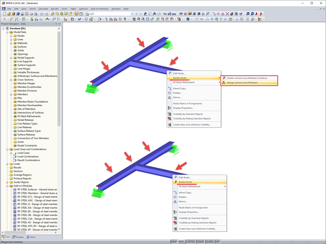
If you want to remove redundant nodes but keep connected objects, you can right-click the relevant node and select the "Delete Nodes" and "Merge Connected Members" options. In addition to members, you can also merge lines in RFEM.

The new "Result Beam" member type in RFEM 5 allows you to determine the load sums of individual floors easily. To do this, model a member in the relevant floor or in all floors, then specify the relevant walls as inclusive objects in the parameters of the result beam. RFEM then integrates the surface internal forces into member internal forces.
The preselection allows you to localize the relevant objects before clicking them.

When using the RF‑GLASS add‑on module, you can define just the geometry in the main program, as well as the load situation of the structural component to be designed. The respective support conditions and all further design-relevant definitions (for example, the layer structure and support conditions), can be further specified in RF‑GLASS.
.png?mw=640&hash=8fd04a597cecae2e434980ce79fc626815a5d98a)
The Aluminum Design Manual (ADM) 2020 was released in February 2020. The ADM 2020 gives guidance for both the allowable strength design (ASD) and load and resistance factor design (LRFD) for aluminum members to ensure reliability and safety for all aluminum structures. This latest standard was integrated in the RFEM/RSTAB add-on module RF-/ALUMINUM ADM. The text below will highlight the applicable updates relevant to the Dlubal programs.

In the existing standard, there were no regulations for the distribution of snow loads for elevated solar thermal and photovoltaic systems on roofs. Only distribution of the loads was advised. It was only with the National Annex DIN EN 1991-1-3/NA: 2019-04 that specific regulations were made for this.

For crane runways with large spans, the horizontal load from skewing is often relevant for the design. This article describes the origin of these forces and the correct input in CRANEWAY. The practical implementation and the theoretical background are discussed.
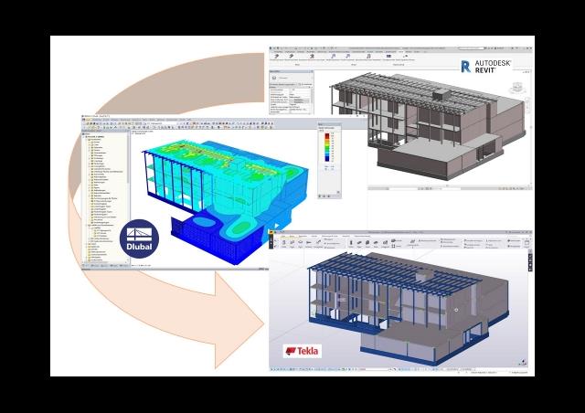
This article discusses the most common BIM interfaces. Adjustments are often necessary during the transition to the structural branch-specific model. The tasks that arise and the tools to address them successfully and quickly are presented.

After running an analysis in RF-/STEEL AISC, the mode shapes for sets of members can be viewed graphically in a separate window. Select the relevant set of members in the result window and click the [Mode Shapes] button.
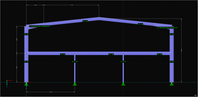
Sections 4.1 and 4.2 of this article series describe the optimization of a frame using the RF‑/STEEL EC3 add-on module. The fifth section explains how to link the module and get the relevant members. The elements already explained in the previous sections will not be described again.

If you want to connect members tangentially to a curved member or a curved surface in RFEM, it is necessary to define the member rotation of the connected members. In order to avoid manual determination, you can display the center point of the curved line and place a node on it. Then, you can select the "Member Rotation via Help node" option and specify the relevant help nodes. Thus, the members are rotated automatically in the defined plane (x-z in our example) and the top edge of the rotated cross-section is parallel to the tangent of the curved line.

As in RFEM, load combinations can be generated automatically in RF‑PIPING. This feature is activated by default and creates the recommended load and result combinations for piping design. It is necessary to assign the relevant action category to load cases in order to generate the correct combinations. To do this, new action categories have been implemented specifically for loads on piping.
Pressure temperature conditions are generated as the sets of the first (second, third, and so on) load case of the "Pressure" category and the first (second, third, and so on) load case of the "Temperature" category. The default setting can be reviewed or adjusted in the "Grouping of Thermal and Internal Pressure Load Cases for Operating Combinations" dialog box. You can access this dialog box by clicking the corresponding button in the "Piping Load Combinations" tab of the "Load Cases and Combinations" dialog box. This dialog box is automatically offered to check your entries in the case of any change of the load case from the "Pressure" or "Temperature" category.
Pressure temperature conditions are generated as the sets of the first (second, third, and so on) load case of the "Pressure" category and the first (second, third, and so on) load case of the "Temperature" category. The default setting can be reviewed or adjusted in the "Grouping of Thermal and Internal Pressure Load Cases for Operating Combinations" dialog box. You can access this dialog box by clicking the corresponding button in the "Piping Load Combinations" tab of the "Load Cases and Combinations" dialog box. This dialog box is automatically offered to check your entries in the case of any change of the load case from the "Pressure" or "Temperature" category.
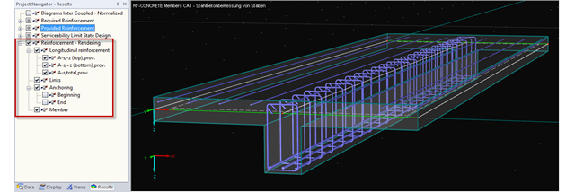
You can display the existing reinforcement of RF-CONCRETE Members not only in the module, but also in the RFEM graphical window and thus show the reinforcement for all members of the relevant RF-CONCRETE case.
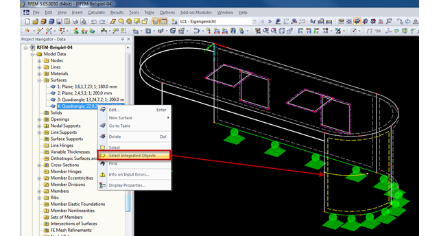
Generally, RFEM automatically detects all objects lying on a surface that are not used for surface definition. Objects integrated into surfaces can be selected using the "Select Integrated Objects" option in the shortcut menu of the relevant surface in Project Navigator. This way, you can easily find in the graphics which objects have already been integrated into a surface, for example.

In RF-STEEL Surfaces, it is possible to display the stresses relevant for the design of welds, for example, according to EN 1993‑1‑8, Figure 4.5. When evaluating the stress components, the local xyz-axis system of the surfaces must be considered.
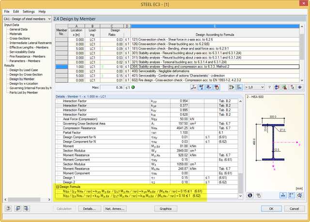
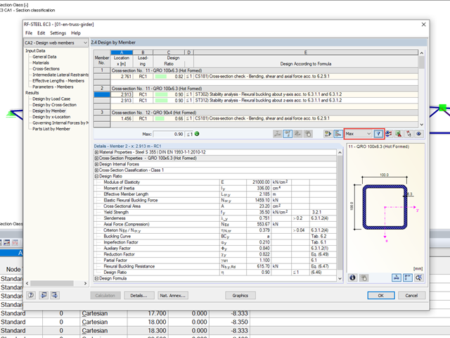
RF-/STEEL EC3 performs the classification, cross‑section designs, serviceability limit state designs, and fire resistance designs of members. For each design, the program shows a result table with the relevant values and classification numbers, including information regarding the respective standard clause. In order to identify the conjunction of various standards easily, there is a final design equation, including all terms, at the end of the table.
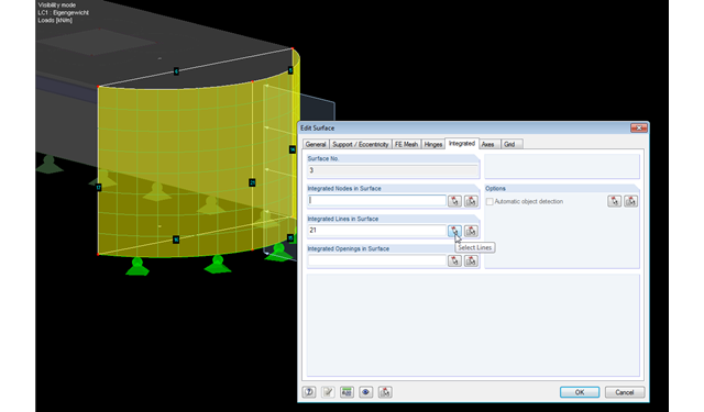
RFEM facilitates modeling by the automatic integration of objects into surfaces. However, it is impossible to integrate the objects automatically in the case of curved surfaces. For manual integration, select the relevant surfaces and click the "Edit Surfaces" option in the shortcut menu; then, in the "Integrated" tab, you can integrate the relevant objects using the "Select" function. This way, you can avoid error messages caused by non‑integrated objects when starting the calculation.
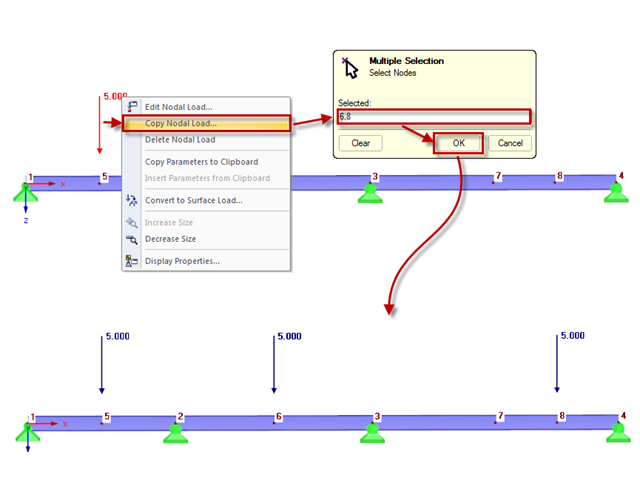
You can quickly copy nodal loads to other nodes using the "Copy Nodal Load" option in the shortcut menu. To do this, select the nodal loads to be copied first, then click the "Copy Nodal Load" option in the shortcut menu. A "Multiple Selection" window appears where you can enter the relevant nodes to which the nodal load is to be copied. After clicking "OK" to close the window, the nodal load is copied.
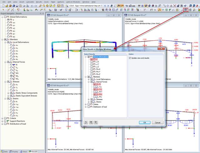
In order to show various results (deformations, internal forces) in multiple windows quickly, you can use the "Arrange Result Windows" function ("Results" menu). A dialog box appears where you can select the relevant results to be displayed.