
You can open the cross-sections in RSECTION using a direct connection, modify them there, and transfer them back to RFEM/RSTAB. Both RSECTION cross-sections and library cross-sections, with the exception of elliptical, semi-elliptical and virtual joists, can be opened and modified directly in RSECTION by clicking a button.
For example, you can thus adjust the reinforcement layout of user-defined RSECTION cross-sections directly in a local RSECTION environment in RFEM/RSTAB. This feature is currently only available for cross-sections with a uniform distribution type. The shear and longitudinal reinforcement defined for library cross-sections is not imported into RSECTION.
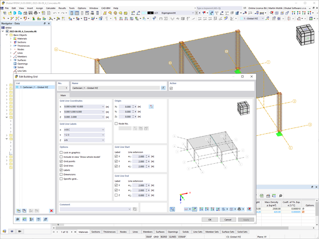
The "Building Grid" guide object supports you in the design of your structure. It features intuitive grid coordinate input and grid line labeling.
You can quickly place grids in space and label them by specifying a graded coordinate code. The grid line end modification allows you to optimize the grid appearance. Furthermore, a preview helps you to define the building grid.
Go to Explanatory Video
Did you know? You can easily define structural modifications in load cases of the Modal Analysis type. This allows you, for example, to individually adjust the stiffnesses of materials, cross-sections, members, surfaces, hinges, and supports. You can also modify stiffnesses for some design add-ons. Once you select the objects, their stiffness properties are adapted to the object type. In this way, you can define them in separate tabs.
Do you want to analyze the failure of an object (for example, a column) in the modal analysis? This is also possible without any problems. Simply switch to the Structure Modification window and deactivate the relevant objects.

Time-dependent concrete properties, such as creep and shrinkage, are very important for your calculation. You can define them directly for the material in the structural analysis program. In the input dialog box, the time course of the creep or shrinkage function is displayed to you graphically. You can easily select the modification of the applied concrete age, for example, due to a temperature treatment.
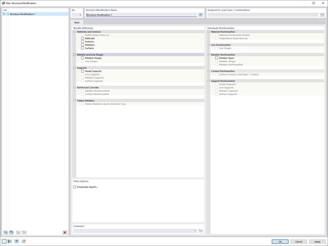
Use the new useful structure modification object to modify or deactivate stiffnesses, nonlinearities, and objects in a clear and load case-dependent way.
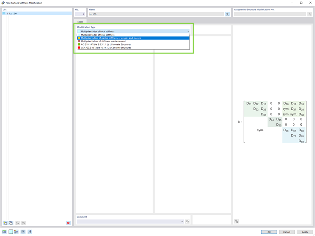
Do you want to modify surface stiffnesses? There are now two new types available for you:
- Multiplication factor of total stiffness
- Multiplication factors of partial stiffnesses, weights, and masses
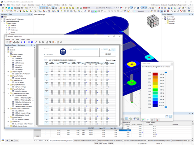
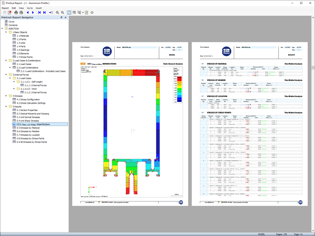
Discover the fundamentally revised and optimized printout report. It offers you the following innovations, among other things:
- Quick creation due to non-modal printout report environment (parallel work in program and report possible)
- Interactive modification of chapters as well as creation of new user-defined chapters
- Import of PDFs, formulas, 3D graphics, and so on
- Output of the design check formulas used in the design (including a reference to the used equation from the standard)
- Modern printout report design
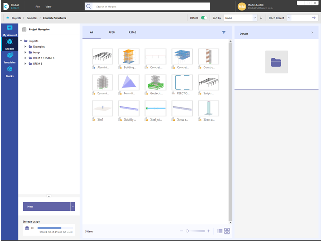
Always keep track of things: The project navigator manages your projects and models of the Dlubal applications in a central location. Have the models displayed clearly in a list form or with a preview image. Furthermore, the program shows you detailed information as a preview, such as file size, model data, modification date, and so on.

Compared to the RF‑/STABILITY (RFEM 5) and RSBUCK (RSTAB 8) add-on modules, the following new features have been added to the Structure Stability add-on for RFEM 6 / RSTAB 9:
- Activation as a property of a load case or a load combination
- Automated activation of the stability calculation via combination wizards for several load situations in one step
- Incremental load increase with user-defined termination criteria
- Modification of the mode shape normalization without recalculation
- Result tables with filter option

- Automatic consideration of masses from self-weight
- Direct import of masses from load cases or load combinations
- Optional definition of additional masses (nodal, linear, or surface masses, as well as inertia masses) directly in the load cases
- Optional neglect of masses (for example, mass of foundations)
- Combination of masses in different load cases and load combinations
- Preset combination coefficients for various standards (EC 8, SIA 261, ASCE 7,...)
- Optional import of initial states (for example, to consider prestress and imperfection)
- Structure Modification
- Consideration of failed supports or members/surfaces/solids
- Definition of several modal analyses (for example, to analyze different masses or stiffness modifications)
- Selection of mass matrix type (diagonal matrix, consistent matrix, unit matrix), including user-defined specification of translational and rotational degrees of freedom
- Methods for determining the number of mode shapes (user-defined, automatic - to reach effective modal mass factors, automatic - to reach the maximum natural frequency - only available in RSTAB)
- Determination of mode shapes and masses in nodes or FE mesh points
- Results of eigenvalue, angular frequency, natural frequency, and period
- Output of modal masses, effective modal masses, modal mass factors, and participation factors
- Masses in mesh points displayed in tables and graphics
- Visualization and animation of mode shapes
- Various scaling options for mode shapes
- Documentation of numerical and graphical results in printout report

In the modal analysis settings, you have to enter all data that are necessary for the determination of the natural frequencies. These are, for example, mass shapes and eigenvalue solvers.
The Modal Analysis add-on determines the lowest eigenvalues of the structure. Either you adjust the number of eigenvalues or let them determined automatically. Thus, you should reach either effective modal mass factors or maximum natural frequencies. Masses are imported directly from load cases and load combinations. In this case, you have the option to consider the total mass, load components in the global Z-direction, or only the load component in the direction of gravity.
You can manually define additional masses at nodes, lines, members, or surfaces. Furthermore, you can influence the stiffness matrix by importing axial forces or stiffness modifications of a load case or load combination.

Have you created the entire structure in RFEM? Very well, now you can assign the individual structural components and load cases to the corresponding construction stages. In each construction stage, you can modify release definitions of members and supports, for example.
You can thus model structural modifications, such as those that occur when bridge girders are successively grouted or when columns are settled. Then, assign the load cases created in RFEM to the construction stages as permanent or non-permanent loads.
Did you know that The combinatorics allows you to superimpose the permanent and non-permanent loads in load combinations. In this way, it is possible for you to determine the maximum internal forces of different crane positions or to consider temporary mounting loads available in one construction stage only.
RSECTION also offers everything you need in terms of overview. You can evaluate and visualize all results in an appealing numerical and graphical form. Selection functions support you in the targeted evaluation.
The printout report corresponds to the high standards of the FEA software RFEM and the frame analysis software RSTAB. Any modifications are updated automatically. You don't have to do anything.

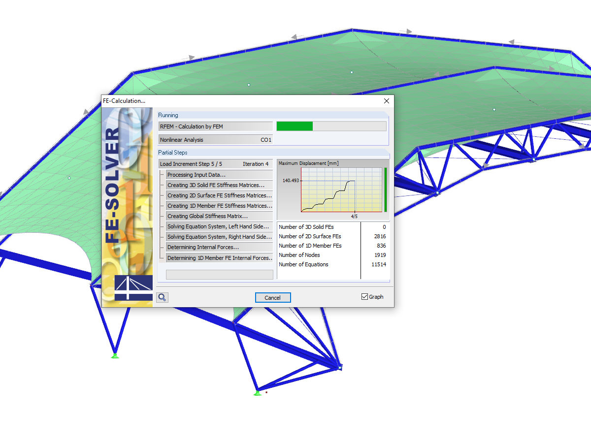
- Calculation of models consisting of member, shell, and solid elements
- Nonlinear stability analysis
- Optional consideration of axial forces from initial prestress
- Four equation solvers for an efficient calculation of various structural models
- Optional consideration of stiffness modifications in RFEM/RSTAB
- Determination of a stability mode greater than the user-defined load increment factor (Shift method)
- Optional determination of the mode shapes of unstable models (to identify the cause of instability)
- Visualization of the stability mode
- Basis for determining imperfection

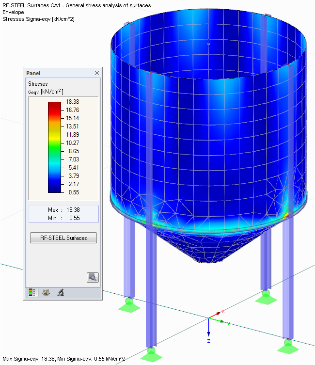
- Determination of principal and basic stresses, membrane and shear stresses, as well as equivalent stresses and equivalent membrane stresses
- Stress analysis for structural surfaces including simple or complex shapes
- Equivalent stresses calculated according to different approaches:
- Shape modification hypothesis (von Mises)
- Shear stress hypothesis (Tresca)
- Normal stress hypothesis (Rankine)
- Principal strain hypothesis (Bach)
- Optional optimization of surface thicknesses and data transfer to RFEM
- Output of strains
- Detailed results of individual stress components and ratios in tables and graphics
- Filter function for solids, surfaces, lines, and nodes in tables
- Transversal shear stresses according to Mindlin, Kirchhoff, or user-defined specifications
- Stress evaluation for welds at connection lines between surfaces (see the Product Feature)
.png?mw=640&hash=9aa98962d5e0d0ed2803b35fcb6a2f87288b0946)
The number of degrees of freedom in a node is no longer a global calculation parameter in RFEM (6 degrees of freedom for each mesh node in 3D models, 7 degrees of freedom for the warping torsion analysis). Thus, each node is generally considered with a different number of degrees of freedom, which leads to a variable number of equations in the calculation.
This modification speeds up the calculation, especially for models where a significant reduction of the system could be achieved (for example, trusses and membrane structures).
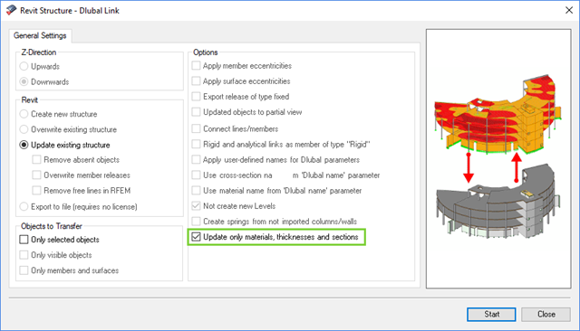
The direct interface with Revit allows you to update the Revit model according to the changes you have made in RFEM or RSTAB. Depending on the modification, the Revit objects may have to be regenerated (deleting the object and subsequent regeneration). The regeneration is performed on the basis of the RFEM/RSTAB model.
If you want to avoid this regeneration, activate the check box 'Update only materials, thicknesses, and sections'. In this case, only the properties of the objects will be adjusted. Changes different from those in material, surface thickness, and section are, however, not considered in this case.
.png?mw=640&hash=8cfd0c4bd093c03de543d147ffbf6f5c9250634a)
- User-defined time diagrams as a function of time, in tabular form, or as harmonic loads
- Combination of the time diagrams with RFEM/RSTAB load cases or combinations (enables definition of nodal, member, and surface loads, as well as free and generated loads varying over time)
- Combination of several independent excitation functions
- Nonlinear time history analysis with the implicit Newmark analysis (RFEM only) or the explicit analysis
- Structural damping using Rayleigh damping coefficients or Lehr's damping
- Direct import of initial deformations from a load case or combination (RFEM only)
- Stiffness modifications as initial conditions; for example, axial force effect, deactivated members (RSTAB only)
- Graphical display of results in a time history diagram
- Export of results in user-defined time steps or as an envelope
- Determination of principal and basic stresses, membrane and shear stresses, as well as equivalent stresses and equivalent membrane stresses
- Stress analysis for structural surfaces including simple or complex shapes
- Equivalent stresses calculated according to different approaches:
- Shape modification hypothesis (von Mises)
- Shear stress hypothesis (Tresca)
- Normal stress hypothesis (Rankine)
- Principal strain hypothesis (Bach)
- Optional optimization of surface thicknesses and data transfer to RFEM
- Serviceability limit state design by checking surface displacements
- Detailed results of individual stress components and ratios in tables and graphics
- Filter function for surfaces, lines, and nodes in tables
- Transversal shear stresses according to Mindlin, Kirchhoff, or user-defined specifications
- Parts list of designed surfaces
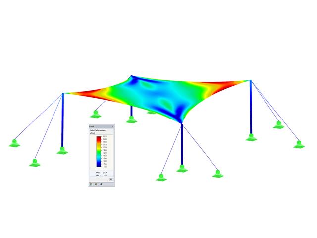
- Planar and geodesic cutting lines
- Flattening of double-curved surface parts of tensioned membranes or pneumatic cushions
- Definition of cutting patterns by using boundary lines which are not required to be connected
- Sophisticated flattening based on the minimum energy theory
- Welding and boundary allowances
- Uniform or linear compensation in warp and weft direction
- Possibility of different compensations for boundary lines
- Adaptable data organisation (any additional modification of input data is considered up to the final "weld")
- Graphical display of cutting patterns
- Statistical information about each cutting pattern (width, length, size)
- Option to automatically generate cutting patterns from cells
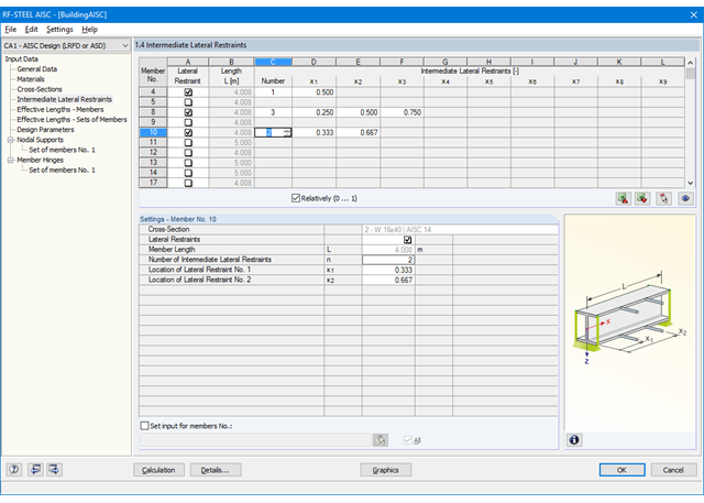
First, it is necessary to decide whether to perform design according to ASD or LRFD. Then, you can enter the load cases, load combinations, and result combinations to be designed. Load combinations according to ASCE 7 can be generated either manually or automatically in RFEM/RSTAB.
In the next steps, you can adjust presettings of lateral intermediate supports, effective lengths, and other standard-specific design parameters, such as the modification factor Cb for lateral-torsional buckling or the shear lag factor. In the case of continuous members, it is possible to define individual support conditions and eccentricities of each intermediate node of single members. A special FEA tool determines critical loads and moments required for the stability analysis.
In connection with RFEM/RSTAB, it is possible to apply the Direct Analysis Method taking into account the influence of the general calculation according to the second-order analysis. In this way, you avoid using special enlargement factors.
All results can be evaluated and visualized in an appealing numerical and graphical form. Selection functions facilitate the targeted evaluation.
The printout report corresponds to the high standards of RFEM and rstab/rstab-9/what-is-rstab RSTAB. Modifications are updated automatically.
All design results and design checks are displayed in detail and in a comprehensible manner. An error log indicates non-designable situations or failed recommendations. Due to the permanent integration in RFEM/RSTAB, subsequent modifications in the structural system and in loading are automatically taken into account for the connections to be checked.
If one of the designs could not be fulfilled, the corresponding line is highlighted in red. The output appears in a short or a long form in the global printout report of RFEM/RSTAB. Furthermore, you can easily export all result tables to MS Excel or in a CSV file. A special transfer menu defines all specifications required for the export.
- Automatic consideration of masses from self-weight
- Direct import of masses from load cases or load combinations
- Optional definition of additional masses (nodal, linear, surface masses, as well as inertia masses)
- Combination of masses in different mass cases and mass combinations
- Preset combination coefficients according to EC 8
- Optional import of normal force distributions (in order to consider prestress, for example)
- Stiffness modification (for example, deactivated members or stiffnesses can be imported from RF-/CONCRETE)
- Consideration of failed supports or members
- Definition of several natural vibration cases (for example, to analyze different masses or stiffness modifications)
- Results of eigenvalue, angular frequency, natural frequency, and period
- Determination of mode shapes and masses in nodes or FE mesh points
- Results of modal masses, effective modal masses, and modal mass factors
- Visualization and animation of mode shapes
- Various scaling options for mode shapes
- Documentation of numerical and graphical results in the printout report
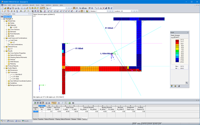
- General stress analysis
- Graphical and numerical results of stresses and stress ratios fully integrated in RFEM
- Flexible design with different layer compositions
- High efficiency due to few entries required
- Flexibility due to detailed setting options for basis and extent of calculations
- A local overall stiffness matrix of the surface in RFEM is generated on the basis of the selected material model and the layers contained. The following material models are available:
- Orthotropic
- Isotropic
- User-defined
- Hybrid (for combinations of material models)
- Option to save frequently used layer structures in a database
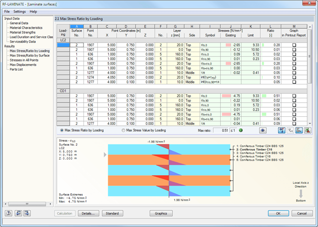
- Determination of basic, shear, and equivalent stresses
- In addition to the basic stresses, the required stresses according to DIN EN 1995-1-1 and the interaction of those stresses are available as results.
- Stress analysis for structural surfaces including simple or complex shapes
- Equivalent stresses calculated according to different approaches:
- Shape modification hypothesis (von Mises)
- Shear stress hypothesis (Tresca)
- Normal stress hypothesis (Rankine)
- Principal strain hypothesis (Bach)
- Calculation of transversal shear stresses according to Mindlin or Kirchhoff, or user-defined specifications
- Serviceability limit state design by checking surface displacements
- User-defined specifications of limit deflections
- Possibility to consider layer coupling
- Detailed results of individual stress components and ratios in tables and graphics
- Results of stresses for each layer in the model
- Parts list of designed surfaces
- Possible coupling of layers entirely without shear
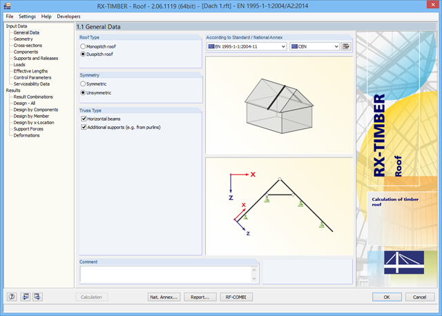
There are various options available for modeling a roof. Graphical representations facilitate the geometry input. Modifications are updated automatically.
In addition, it is possible to consider cross‑section weakening on supports. Optionally, you can define if the design of support pressure on the rafter side should be performed.
Permanent loads (for example, roof structure) can be entered using the comprehensive and extensible material library. Loads due to cantilevers and collars/ties can be entered separately. Generators integrated in RX-TIMBER Purlin allow for convenient generation of various wind and snow load cases. You can manually add any concentrated and distributed loads.
Load cases are displayed graphically and superimposed in automatically generated load combinations according to EC 5. For stability and serviceability limit state designs, you can change the data manually, for example, for example, for cantilevers (roof overhang), it is necessary to ignore the SLS.
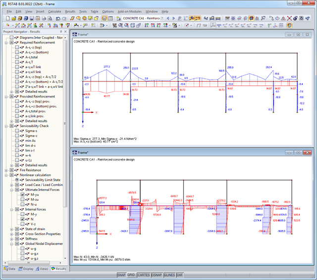
After the calculation, the module shows clearly arranged tables listing the required reinforcement and the results of the serviceability limit state design. All intermediate values are included in a comprehensible manner. In addition to the tables, current stresses and strains in a cross‑section are represented graphically.
The reinforcement proposals of the longitudinal and the shear reinforcement, including sketches, are documented in accordance with current practice. It is possible to edit the reinforcement proposal and to adjust, for example, the number of members and the anchorage. The modifications will be updated automatically.
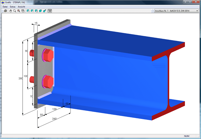
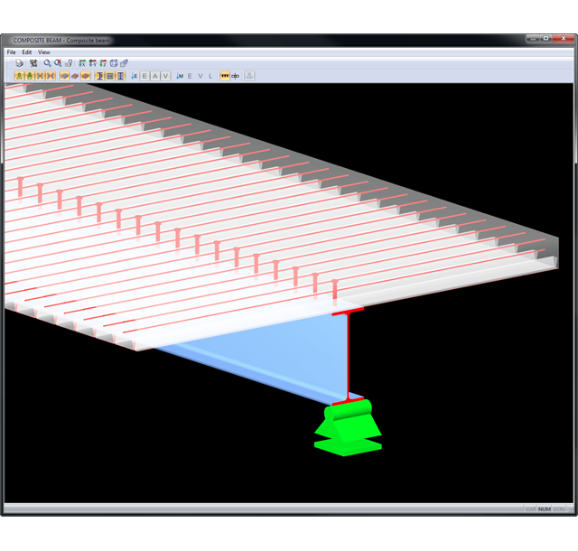
A concrete cross‑section, including reinforcement, can be visualized in a 3D rendering. This way, the program provides an optimal documentation option to create reinforcement drawings, including steel schedule.
Crack width analyzes are performed using the selected reinforcement of internal forces in the serviceability limit state. The result output covers steel stresses, the minimum reinforcement, limit diameters, and the maximum bar spacing, as well as crack spacing and the maximum crack widths.
As a result of the nonlinear calculation, there are the ultimate limit states of the cross‑section with defined reinforcement (determined linear elastically) as well as effective deflections of the member considering stiffness in cracked state.
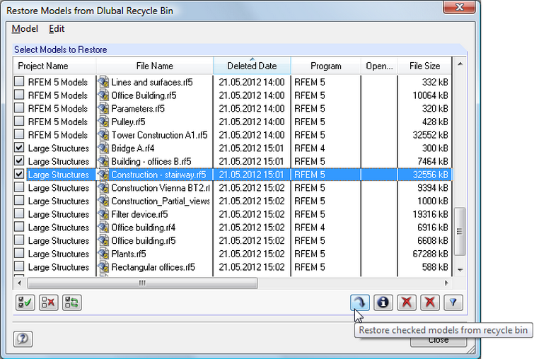
The project manager can also manage subprojects. The manager displays the relevant information of each model; for example, the date of creation and latest modification of a structure, as well as the related user name. In addition, you can see the dimensions and weight of each structure. It is possible to restore accidentally deleted projects from the integrated recycle bin.
Results are displayed in result tables sorted by required designs. Clear arrangement of the results allows for easy orientation and evaluation.
Ultimate Limit State Design:
- Bending and shear force resistance with interaction
- Partial shear connecting of ductile and non-ductile connecting elements
- Determination of required shear connectors and their distribution
- Design of longitudinal shear force resistance
- Design of connection with shear connectors and of connector perimeter
- Results of governing support reactions for construction and composite stage, including loads of construction supports
- Lateral-torsional buckling analysis (for continuous beams and cantilevered girders)
- Check of cross-section classes as well as of plastic and elastic cross-section properties
Serviceability limit state design:
- Deflection Analysis
- Deformations and initial pre-cambering determined with ideal cross-section properties from creep and shrinkage
- Analysis of natural frequencies
- Crack width analysis
- Determination of support forces
All data are documented in a clearly arranged printout report, including graphics. In case of any modification, the printout report is updated automatically. COMPOSITE-BEAM is a stand-alone program and does not require the RSTAB license.
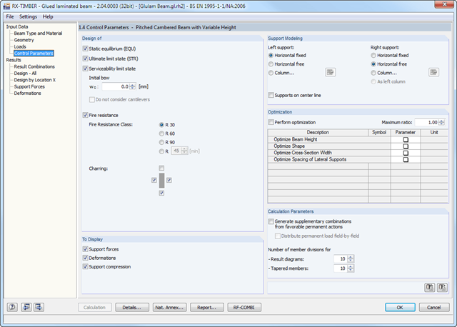
In RX-TIMBER Glued-Laminated Beam, the following calculation settings are available:
- Design of ULS, SLS, and/or fire resistance
- Selection of designs to be performed
- Determination of displaying support forces and deformations
- Adjusting the recommended limit values for the deformation analyses
- Definition of parameters for the fire resistance design performed according to the simplified method (optionally for F 30‑B, F 60‑B, F 90‑B, and user‑defined)
- Determination of tilting moment for pinned support
- Definition of support conditions for a beam
- Beam optimization by means of:
- Beam depth modification
- Modification of beam scene
- cross-section width
- Spacing of lateral supports