22 Wyniki
Wyświetl wyniki:
Sortuj według:
W inżynierii konstrukcyjnej przewidywanie wpływu turbulentnego przepływu wiatru na konstrukcje ma kluczowe znaczenie dla bezpieczeństwa i wydajności. Modelowanie turbulencji w Computational Fluid Dynamics (CFD) pomaga w symulacji tych interakcji. Inżynierowie muszą wybrać praktyczny model turbulencji, równoważąc wydajność, dokładność i możliwości zastosowania. Typowe modele to uśredniony Navier-Stokes (RANS), niestabilny uśredniony Navier-Stokes (URANS) oraz Delayed Detached Eddy Simulation (DDES). Program RANS jest niezawodnym i ekonomicznym rozwiązaniem w przypadku stałych przepływów, URANS rejestruje zależne od czasu zjawiska dla średnich niestateczności, a DDES, hybryda RANS i symulacji dużych wirów (LES), rozwiązuje złożone struktury turbulentne. Zrozumienie mocnych stron i ograniczeń każdego modelu pomoże inżynierom wybrać najlepsze podejście do swoich potrzeb.
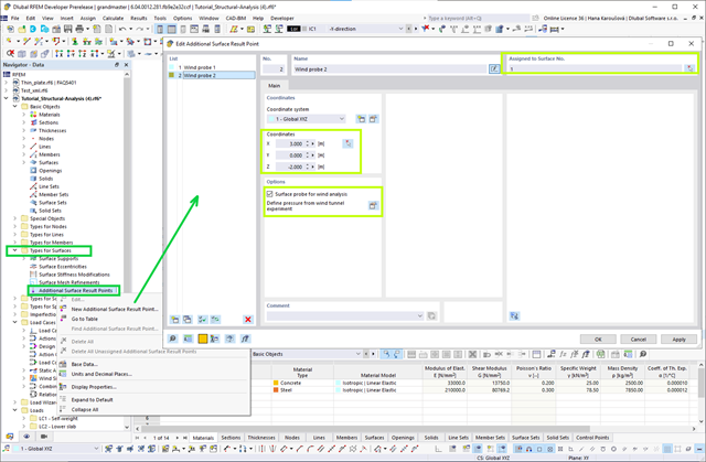
Jeśli dostępne są wyniki parcia powierzchniowego na budynek wywołane wiatrem, można je zastosować w modelu konstrukcyjnym w programie RFEM 6, przetworzonym przez RWIND 2 i wykorzystać jako obciążenia wiatrem do analizy statycznej w RFEM 6.
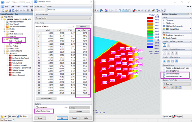
Za pomocą programów RWIND 2 i RFEM 6 można teraz obliczać obciążenia wiatrem na podstawie zmierzonego eksperymentalnie ciśnienia wiatru na powierzchnie. Zasadniczo dostępne są dwie metody interpolacji, umożliwiające rozłożenie ciśnienia mierzonego w izolowanych punktach na powierzchnie. Żądany rozkład ciśnienia można uzyskać za pomocą odpowiedniej metody i ustawień parametrów.
Stworzenie przykładu walidacyjnego dla obliczeniowej mechaniki płynów (CFD) jest kluczowym krokiem w zapewnieniu dokładności i wiarygodności wyników symulacji. This process involves comparing the outcomes of CFD simulations with experimental or analytical data from real-world scenarios. The objective is to establish that the CFD model can faithfully replicate the physical phenomena it is intended to simulate.
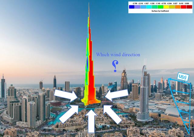
Kierunek wiatru odgrywa kluczową rolę w kształtowaniu wyników symulacji komputerowej mechaniki płynów (CFD) oraz w projektowaniu konstrukcyjnym budynków i infrastruktury. Jest to decydujący czynnik w ocenie interakcji sił wiatru z konstrukcjami, wpływających na rozkład ciśnienia wiatru, a w konsekwencji na reakcje konstrukcji.
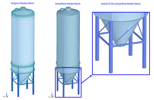
Obliczenia CFD są na ogół bardzo złożone. Dokładne obliczenia przepływu wiatru wokół skomplikowanych konstrukcji są bardzo czasochłonne i kosztowne. W wielu zastosowaniach inżynierskich wysoka dokładność nie jest wymagana, a nasz program CFD RWIND 2 pozwala w takich przypadkach uprościć model konstrukcji i znacznie zredukować koszty. W tym artykule odpowiedzi na niektóre pytania dotyczące uproszczenia.
Zgodność z przepisami budowlanymi, takimi jak Eurokod, jest niezbędna dla zapewnienia bezpieczeństwa, integralności konstrukcji i trwałości budynków i konstrukcji. Obliczeniowa mechanika płynów (CFD) odgrywa istotną rolę w tym procesie, symulując zachowanie płynów, optymalizując projekty i pomagając architektom i inżynierom w spełnieniu wymagań Eurokodu związanych z analizą obciążenia wiatrem, wentylacją naturalną, bezpieczeństwem pożarowym i efektywnością energetyczną. Integrując CFD z procesem projektowania, profesjonaliści mogą tworzyć bezpieczniejsze, wydajniejsze i zgodne z przepisami budynki, które spełniają najwyższe standardy konstrukcyjne i projektowe w Europie.
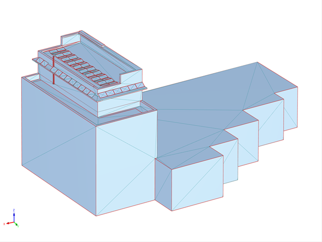
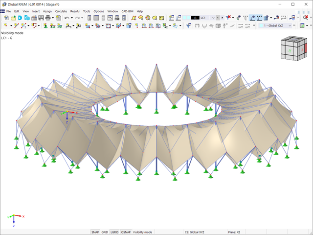
Modele wielkoskalowe to modele, które zawierają skale wielowymiarowe, a tym samym wymagają dużej mocy obliczeniowej. Z tego artykułu dowiesz się, jak uprościć i zoptymalizować obliczenia takich modeli w odniesieniu do pożądanych wyników.
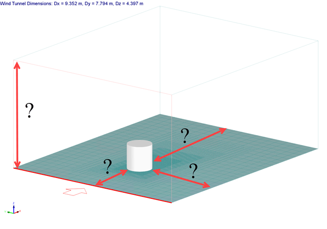
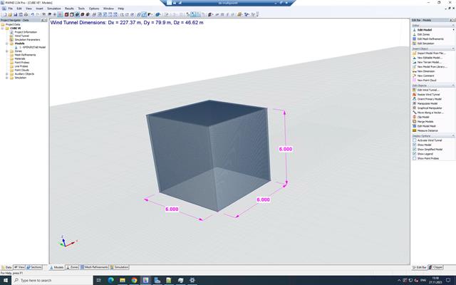
Rozmiar domeny obliczeniowej (rozmiar tunelu aerodynamicznego) jest ważnym aspektem symulacji wiatru, który ma znaczący wpływ na dokładność, a także na koszt symulacji CFD.
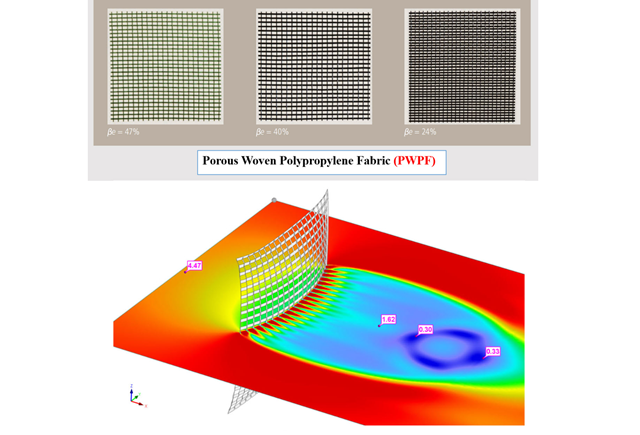
W obliczeniowej mechanice płynów (CFD) można modelować złożone powierzchnie, które nie są całkowicie stałe, używając porowatego i przepuszczalnego medium. W świecie rzeczywistym mogą to być na przykład wiatrochrony, siatki druciane, perforowane fasady i okładziny, żaluzje, przęsła (stosy poziomych walców) i tak dalej.

Osłony przeciwwiatrowe to specjalne konstrukcje tekstylne, które mają za zadanie chronić środowisko przed szkodliwymi cząsteczkami chemicznymi, jak również ograniczać erozję wietrzną, przyczyniając się do ochrony cennych zasobów. RFEM i RWIND są używane do analizy konstrukcji wiatrowej dla jednostronnej interakcji płyn-konstrukcja (FSI).
W tym artykule pokazano, jak wymiarować osłony przeciwwiatrowe przy użyciu programów RFEM i RWIND.
W tym artykule pokazano, jak wymiarować osłony przeciwwiatrowe przy użyciu programów RFEM i RWIND.
RWIND 2 to program do generowania obciążeń wiatrem w oparciu o CFD (Computational Fluid Dynamics). Symulacja numeryczna przepływu wiatru jest generowana wokół dowolnego budynku, w tym budynku o nieregularnej lub unikalnej geometrii, w celu określenia obciążeń wiatrem na powierzchnie i pręty. RWIND 2 może być zintegrowany z programem RFEM/RSTAB w celu przeprowadzenia analizy statyczno-wytrzymałościowej lub jako samodzielna aplikacja.
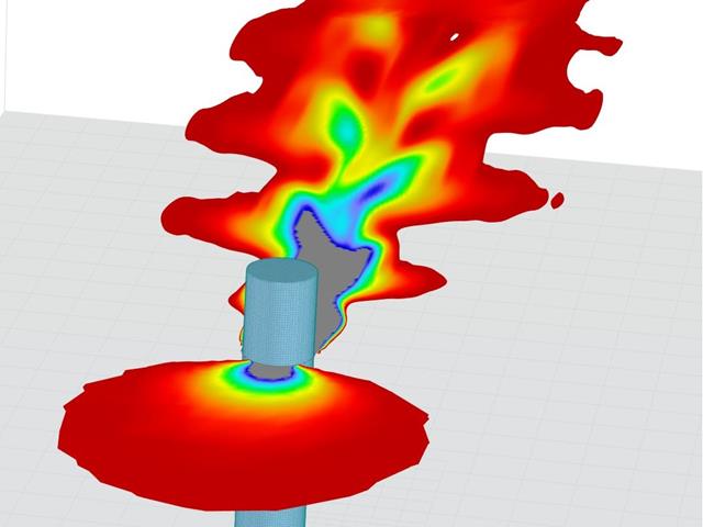
Modelowanie ulicy wirowej Karmana w RWIND
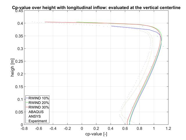
W tym artykule porównujemy wyniki z programów RWIND, ABAQUS i ANSYS z badaniem w tunelu aerodynamicznym przy użyciu prostego geometrycznie modelu.
RWIND 2 to program do generowania obciążeń wiatrem w oparciu o CFD (Computational Fluid Dynamics). Symulacja numeryczna przepływu wiatru jest generowana wokół dowolnego budynku, w tym o nieregularnej lub niepowtarzalnej geometrii, w celu określenia obciążenia wiatrem powierzchni i prętów. RWIND 2 może być zintegrowany z programem RFEM/RSTAB w celu przeprowadzenia analizy statyczno-wytrzymałościowej lub jako samodzielna aplikacja.
Ponieważ w Eurokodzie nie uwzględniono wiatru oddziałującego na konstrukcje otwarte z jednej strony, odniesiono się do czterech przypadków z niemieckiej normy DIN 1055, część czwarta.
Konstrukcje różnie reagują na działanie wiatru, w zależności od sztywności, masy i tłumienia. Zasadniczo rozróżnia się budynki, które są podatne na drgania oraz takie, które nie są na nie podatne.
Dzięki ciągłemu rozwojowi technologii komputerowych analiza statyczna i projektowanie są dziś ściśle związane z narzędziami cyfrowymi. Z każdym nowym opracowaniem projektanci są w stanie przekraczać kolejne granice tego, co jeszcze niedawno było nieosiągalne.
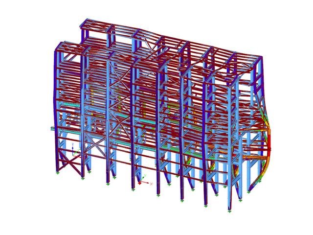
Konstrukcje budowlane są z natury trójwymiarowe. W przeszłości przeprowadzanie obliczeń na układach trójwymiarowych z punktu widzenia praktycznego było bardzo trudne. Dlatego konstrukcje upraszczano i dzielono na płaskie podukłady. Wraz ze wzrostem wydajności komputerów oraz związanego z nimi oprogramowania, coraz częściej możemy zrezygnować z tych uproszczeń. Trend ten wzmacniają nowe technologie cyfrowe, takie jak Building Information Modelling (BIM) czy też nowe możliwości tworzenia realistycznych wizualizacji trójwymiarowych. Czy jednak rzeczywiście model 3D mają przewagę nad podejściem tradycyjnym czy to tylko kwestia aktualnej mody? Poniżej przedstawiono niektóre argumenty przemawiające za stosowaniem modeli 3D konstrukcji.
Wszystkie budynki to konstrukcje wystawione na działanie wiatru. Przepływ powietrza wokół nich wywołuje określone obciążenia na powierzchniach zewnętrznych, które są wykorzystywane w analizie statyczno-wytrzymałościowej.
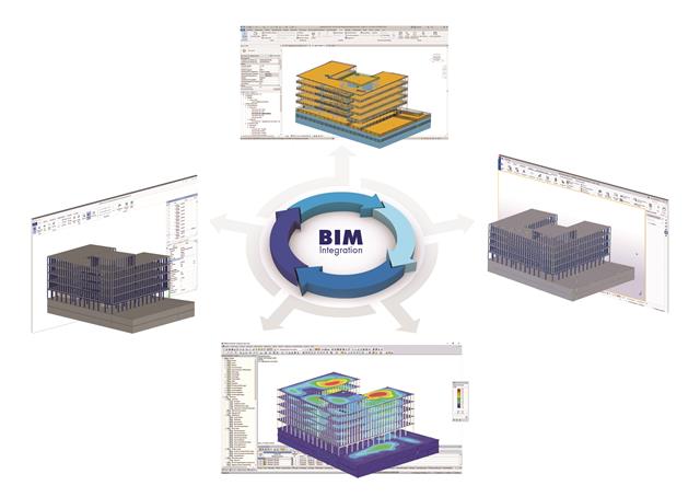
Przemysł budowlany podlega coraz dalej idącej digitalizacji. Konstruktorzy, jedna z mniej licznych grup w branży budowlanej, z reguły nie od razu dołączają do najnowszych trendów. Często nie bez przyczyny. Wiele osób uważa to za powód, dla którego zastosowanie metod BIM nie jest jeszcze standardem w projektowaniu konstrukcji. Jednakże ostatnie kilka lat pokazało, że rozpoczął się proces zmiany w mentalności a konstruktorzy coraz częściej sięgają do nowych trendów w technologii cyfrowej i wykorzystują je w swoich projektach.
.png?mw=640&hash=2c777f8924370109f41757e8517fd5d08108c956)
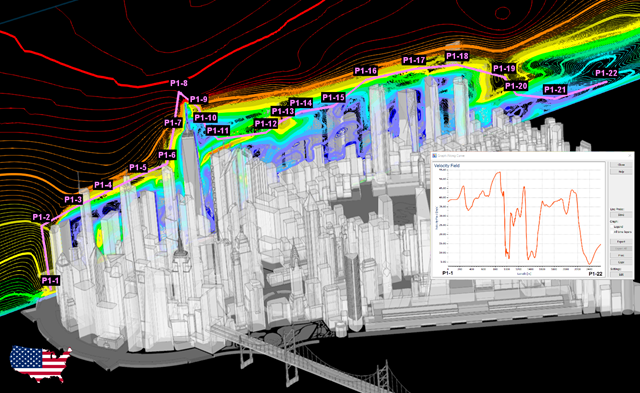
Poniższe opracowanie porównuje ciśnienie wiatru na wysoki budynek, uzyskane przez RWIND Simulation z wynikami opublikowanymi przez Dagnew et al. podczas11th Americas Conference on Wind Engineering w czerwcu 2009 r. W niniejszym artykule jako model wykorzystano budynek Commonwealth Advisory Aeronautical Council (CAARC), a wyniki kilku różnych metod numerycznych porównano z danymi eksperymentalnymi uzyskanymi z tuneli aerodynamicznych.