80 Wyniki
Wyświetl wyniki:
Sortuj według:

Parametry załączników krajowych (NA) do Eurokodu 3 z następujących krajów są zintegrowane:
-
 DIN EN 1993-1-1/NA:2016-04 (Niemcy)
 -
 ÖNORM EN 1993-1-1/NA:2015-12 (Austria)
 -
 SN EN 1993-1-1/NA:2016-07 (Szwajcaria)
 -
 BDS EN 1993-1-1/NA:2015-10 (Bułgaria)
 -
 BS EN 1993-1-1/NA:2016-07 (Wielka Brytania)
 -
 CEN EN 1993-1-1/2015-06 (Unia Europejska)
 -
 CYS EN 1993-1-1/NA:2015-07 (Cypr)
 -
 CSN EN 1993-1-1/NA:2016-06 (Republika Czeska)
 -
 DS EN 1993-1-1/NA:2015-07 (Dania)
 -
 ELOT EN 1993-1-1/NA:2017-01 (Grecja)
 -
 EVS EN 1993-1-1/NA:2015-08 (Estonia)
 -
 HRN EN 1993-1-1/NA:2016-03 (Chorwacja)
 -
 I S. EN 1993-1-1/NA:2016-03 (Irlandia)
 -
 ILNAS EN 1993-1-1/NA:2015-06 (Luksemburg)
 -
 IST EN 1993-1-1/NA:2015-11 (Islandia)
 -
 LST EN 1993-1-1/NA:2017-01 (Litwa)
 -
 LVS EN 1993-1-1/NA:2015-10 (Łotwa)
 -
 MS EN 1993-1-1/NA:2010-01 (Malezja)
 -
 MSZ EN 1993-1-1/NA:2015-11 (Węgry)
 -
 NBN EN 1993-1-1/NA:2015-07 (Belgia)
 -
 NEN EN 1993-1-1/NA:2016-12 (Holandia)
 -
 NF EN 1993-1-1/NA:2016-02 (Francja)
 -
 NP EN 1993-1-1/NA:2009-03 (Portugalia)
 -
 NS EN 1993-1-1/NA:2015-09 (Norwegia)
 -
 PN EN 1993-1-1/NA:2015-08 (Polska)
 -
 SFS EN 1993-1-1/NA:2015-08 (Finlandia)
 -
 SIST EN 1993-1-1/NA:2016-09 (Słowenia)
 -
 SR EN 1993-1-1/NA:2016-04 (Rumunia)
 -
 SS EN 1993-1-1/NA:2019-05 (Singapur)
 -
 SS EN 1993-1-1/NA:2015-06 (Szwecja)
 -
 STN EN 1993-1-1/NA:2015-10 (Słowacja)
 -
 TKP EN 1993-1-1/NA:2015-04 (Białoruś)
 -
 UNE EN 1993-1-1/NA:2016-02 (Hiszpania)
 -
 UNI EN 1993-1-1/NA:2015-08 (Włochy)
- Proste definiowanie etapów budowy konstrukcji w RFEM wraz z wizualizacją
- Dodawanie, usuwanie, modyfikowanie i reaktywacja elementów prętowych, powierzchniowych i bryłowych oraz ich właściwości (np. przeguby prętowe i liniowe, stopnie swobody dla podpór itp.)
- Ręczna oraz automatyczna kombinatoryka obciążeń na poszczególnych etapach budowy konstrukcji (np. w celu uwzględnienia obciążeń montażowych, tymczasowych urządzeń dźwigowych itp.)
- Uwzględnienie wpływów nieliniowych, takich jak uszkodzenie prętów rozciąganych lub nieliniowe zachowanie podpór
- Interakcja z innymi rozszerzeniami, takimi jak z. B. Nieliniowe zachowanie materiału, Stateczność konstrukcji, -rstab-9/additional-analyses/form-finding/form-finding itd.
- Wyświetlanie wyników w postaci numerycznej i graficznej dla poszczególnych etapów budowy
- Szczegółowy protokół wydruku wraz z dokumentacją wszystkich danych konstrukcyjnych i obciążeń dla każdego etapu budowy

Czy udało Ci się utworzyć całą konstrukcję w programie RFEM? Dobrze, teraz można przypisać poszczególne elementy konstrukcyjne i przypadki obciążeń do odpowiednich etapów budowy. Na każdym etapie budowy można modyfikować na przykład definicje zwolnień prętów i podpór.
Pozwala to na modelowanie zmian konstrukcyjnych, na przykład podczas betonowania dźwigarów mostowych lub osiadania słupów. Przypadki obciążeń utworzone w programie RFEM należy następnie przydzielić do etapów budowy jako obciążenia stałe lub przejściowe.
Czy wiecie, że...? Kombinatoryka umożliwia nakładanie obciążeń stałych i przejściowych w kombinacjach obciążeń. W ten sposób można określić maksymalne siły wewnętrzne dla różnych pozycji dźwigu lub uwzględnić tymczasowe obciążenia montażowe dostępne tylko w jednym etapie budowy.

Jeżeli między idealnym układem a układem, który uległ deformacji z poprzedniego etapu budowy, pojawią się różnice w geometrii, są one porównywane w programie. Następujące po sobie kolejne etapy budowy obliczane są na bazie układu konstrukcyjnego z odkształceniami i obciążeniami wynikającymi z poprzednich etapu budowy. Obliczenia te są nieliniowe.

Czy obliczenia zakończyły się pomyślnie? Wyniki poszczególnych etapów budowy można teraz wyświetlać graficznie oraz w tabelach w programie RFEM. Ponadto program RFEM umożliwia uwzględnienie etapów budowy w kombinatoryce i uwzględnienie ich w dalszych obliczeniach.
_(1).png?mw=640&hash=415f7bbaf70e41679bb0106e1cf91eaa8c493ec9)
- Automatyczne generowanie modeli do analizy ES: rozszerzenie automatycznie tworzy w tle model elementów skończonych (ES) połączenia stalowego.
- Uwzględnienie wszystkich sił wewnętrznych: Obliczenia obejmują wszystkie siły wewnętrzne (N , Vy, Vz ,My, Mz, MT ) i nie są ograniczone do obciążeń płaskich.
- Automatyczne przenoszenie obciążeń: Wszystkie kombinacje obciążeń są automatycznie przenoszone do modelu analitycznego ES połączenia. Obciążenia są przenoszone bezpośrednio z programu RFEM, dzięki czemu ręczne wprowadzanie danych nie jest konieczne.
- Wydajne modelowanie: Rozszerzenie pozwala zaoszczędzić czas podczas modelowania złożonych sytuacji związanych z połączeniami. Utworzony model analityczny ES można również zapisać i wykorzystać do własnych szczegółowych analiz.
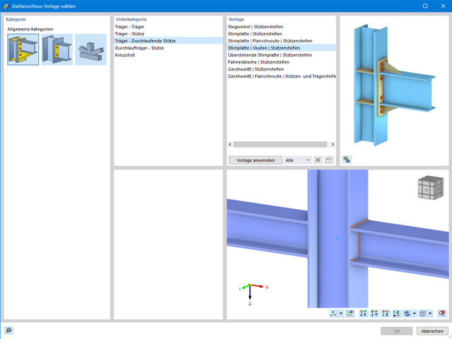
- Rozszerzalna biblioteka: Dostępna jest obszerna, rozszerzalna biblioteka zawierająca wstępnie zdefiniowane szablony połączeń stalowych.
- Szerokie zastosowanie: Rozszerzenie jest odpowiednie do tworzenia połączeń każdego typu i kształtu, jest kompatybilne z prawie wszystkimi przekrojami walcowanymi, spawanymi, złożonymi i cienkościennymi.

- Wybór węzłów w modelu RFEM, automatyczne rozpoznawanie i przydzielanie prętów połączonych z wybranym węzłem
- Dostępnych jest wiele wstępnie zdefiniowanych elementów ułatwiających wprowadzanie typowych komponentów połączeń (np. blachy czołowe, żebra usztywniające)
- Uniwersalne komponenty bazowe (płyty, spoiny, płaszczyzny pomocnicze) do odwzorowania złożonych geometrii połączeń
- Użytkownik nie musi ręcznie edytować modelu MES połączenia, podstawowe ustawienia obliczeń można zmienić w oknie konfiguracji połączenia
- Automatyczne dostosowywanie geometrii połączenia, nawet w przypadku późniejszej edycji prętów, z uwagi na parametryczną definicję położenia komponentów względem siebie
- Równolegle do wprowadzania danych program przeprowadza kontrolę poprawności, aby szybko wykryć brakujące dane wejściowe lub kolizje elementów.
- Wizualizacja geometrii połączenia, która jest aktualizowana równolegle z wprowadzaniem danych
Program wspiera Cię: Moduł określa siły w śrubach na podstawie modelu analitycznego ES i analizuje je automatycznie. Rozszerzenie przeprowadza obliczenia nośności śrub dla przypadków uszkodzeń, takich jak rozciąganie, ścinanie, docisk otworu i przebicie, zgodnie z normą i wyświetla w przejrzysty sposób wszystkie wymagane współczynniki.
Chcesz przeprowadzić wymiarowanie spoin? Spoiny są modelowane jako sprężysto-plastyczne elementy powierzchniowe, a ich naprężenia są odczytywane z modelu analitycznego ES. Kryterium plastyczności ma reprezentować zniszczenie zgodnie z AISC J2-4, J2-5 (wytrzymałość spoin) i J2-2 (wytrzymałość metalu podstawowego). Obliczenia można przeprowadzić z zastosowaniem częściowych współczynników bezpieczeństwa określonych w załączniku krajowym do normy EN 1993-1-8.
Płyty w połączeniu są wymiarowane w sposób plastyczny poprzez porównanie istniejącego odkształcenia plastycznego z dopuszczalnym odkształceniem plastycznym. Domyślne ustawienie wynosi 5% zgodnie z EN 1993-1-5, Załącznik C, ale można to zmienić według specyfikacji użytkownika, a także 5% dla AISC 360.
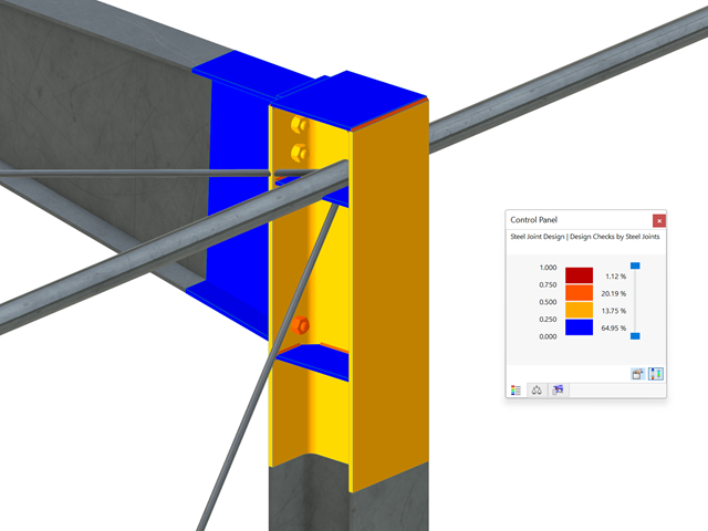
Wszystkie istotne wyniki można wyświetlić w modelu ES. W takim przypadku można filtrować wyniki osobno według odpowiednich komponentów.
Ponadto program RFEM zapewnia wszystkie kontrole obliczeń w formie tabelarycznej wraz z wyświetlaniem zastosowanych wzorów. W razie potrzeby tabele wyników można przenieść do protokołu wydruku programu RFEM.
W porównaniu z modułem dodatkowym RF-/STAGES (RFEM 5) do rozszerzenia Analiza etapów budowy (CSA) dla programu RFEM 6 dodano następujące nowe funkcje:
- Uwzględnienie etapów budowy na poziomie programu RFEM
- Integracja analizy etapu budowy z kombinatoryką w programie RFEM
- Wprowadzono podparcie dla dodatkowych elementów konstrukcyjnych, takich jak przeguby liniowe
- Analiza alternatywnych procesów konstrukcyjnych w modelu
- Ponowna aktywacja elementów konstrukcyjnych
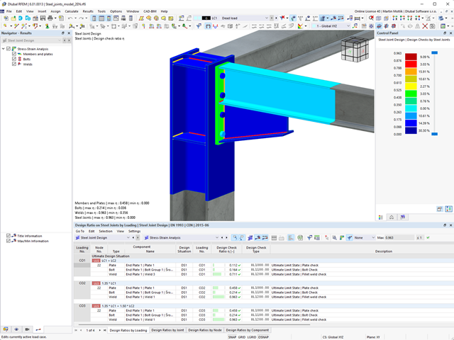
Pracujesz z połączeniami stalowymi? Rozszerzenie Połączenia stalowe dla programu RFEM ułatwia analizę połączeń stalowych za pomocą modelu ES. Modelowanie przebiega całkowicie automatycznie w tle. Proces można jednak kontrolować poprzez proste i wygodne wprowadzanie elementów. Następnie należy wykorzystać naprężenia określone w modelu ES do wymiarowania elementów zgodnie z EN 1993-1-8 (wraz z załącznikami krajowymi).

Projektowanie konstrukcji betonowych | Wykres interakcji My-Mz-N (3D) przekrojów z betonu zbrojonego
Na pytanie 'Ile można przewozić?' zazwyczaj odpowiada 'Tak'. Do graficznego przedstawiania stanu granicznego nośności przekrojów żelbetowych wymagany jest trójwymiarowy wykres interakcji momentu-momentu-siła osiowa. Oprogramowanie do analizy statyczno-wytrzymałościowej firmy Dlubal właśnie to oferuje.
Dzięki dodatkowemu wyświetleniu oddziaływania obciążenia można łatwo rozpoznać lub zwizualizować przekroczenie granicznej nośności przekroju żelbetowego. Ponieważ możesz kontrolować właściwości wykresu, możesz dostosować wygląd wykresu My-Mz-N do swoich potrzeb.

Czy wiesz, że wykresy interakcji moment-siła (wykresy MN) można wyświetlić również graficznie? Umożliwia to wyświetlenie nośności przekroju w przypadku interakcji momentu zginającego i siły osiowej. Oprócz wykresów interakcji związanych z osiami przekroju (wykres My-N i wykres Mz-N) można również wygenerować indywidualny wektor momentów w celu utworzenia wykresu interakcji Mres -N. Płaszczyznę przekroju wykresów MN można wyświetlić na wykresie interakcji 3D.Program wyświetla odpowiednie pary wartości stanu granicznego nośności w tabeli. Tabela jest dynamicznie powiązana z wykresem, dzięki czemu wybrany punkt graniczny jest również wyświetlany na wykresie.

Czy chcesz określić nośność przekroju żelbetowego na zginanie dwukierunkowe? W tym celu należy najpierw aktywować wykres interakcji moment-moment (wykres My-Mz). Wykres My-Mz przedstawia poziomy przekrój przez trójwymiarowy wykres dla określonej siły osiowej N. Dzięki połączeniu z trójwymiarowym wykresem interakcji można tam również zwizualizować płaszczyznę przekroju.
.png?mw=640&hash=5a991f211d984ac624978f514e70c53da263e5d9)
W zależności od siły osiowej N, można wygenerować linię krzywizny momentu dla dowolnego wektora momentu. Program pokazuje również pary wartości wyświetlanego wykresu w tabeli. Ponadto można aktywować jako dodatkowy wykres sieczny i sztywność styczną przekroju żelbetowego, należące do wykresu krzywizny momentu.
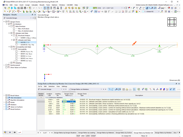
Program do analizy statyczno-wytrzymałościowej zapewnia przejrzysty przegląd wszystkich przeprowadzonych kontroli obliczeń dla określonej normy obliczeniowej. Dla każdego warunku projektowego należy określić kryterium obliczeniowe. Oprócz sprawdzania stanu granicznego nośności i użytkowalności program sprawdza zasady projektowania określone w normie. Dla każdej kontroli obliczeń są określone szczegóły obliczeń, w tym wartości początkowe, wyniki pośrednie i wyniki końcowe. Proces obliczeń wraz z zastosowanymi wzorami, standardowymi źródłami i wynikami szczegółowo przedstawiony jest w oknie informacyjnym w szczegółach obliczeń.

Istniejące naprężenia i odkształcenia przekroju betonowego i zbrojenia można wyświetlić w postaci obrazu naprężeń 3D lub grafiki 2D. W zależności od tego, które wyniki zostaną wybrane w drzewie wyników, naprężenia lub odkształcenia są wyświetlane w zdefiniowanym zbrojeniu podłużnym pod oddziaływaniami obciążeń lub granicznymi siłami wewnętrznymi.

Właściwości betonu, zależne od czasu, takie jak pełzanie i skurcz, są bardzo ważne dla obliczeń. Można je zdefiniować bezpośrednio dla materiału w programie do analizy statyczno-wytrzymałościowej. W oknie dialogowym do wprowadzania danych wyświetlany jest przebieg czasowy funkcji pełzania lub skurczu. Można łatwo wybrać modyfikację zastosowanego wieku betonu, na przykład ze względu na obróbkę termiczną.

Odkształcenie prętów i powierzchni jest określane z uwzględnieniem zarysowanego (stan II) lub niezarysowanego (stan I) przekroju żelbetowego. Podczas określania sztywności można uwzględnić usztywnienie przy rozciąganiu między rysami, zwane 'usztywnieniem przy rozciąganiu', zgodnie z zastosowaną normą obliczeniową.
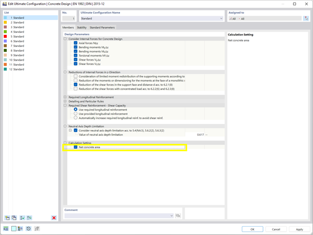
Podczas wymiarowania przekroju można bezpośrednio określić, czy powierzchnia betonowa zostanie zastosowana za prętami zbrojeniowymi, czy też zostanie odjęta od przekroju betonowego. Istnieje możliwość obliczenia przekroju betonu netto, zwłaszcza w przypadku przekroju silnie zbrojonego.
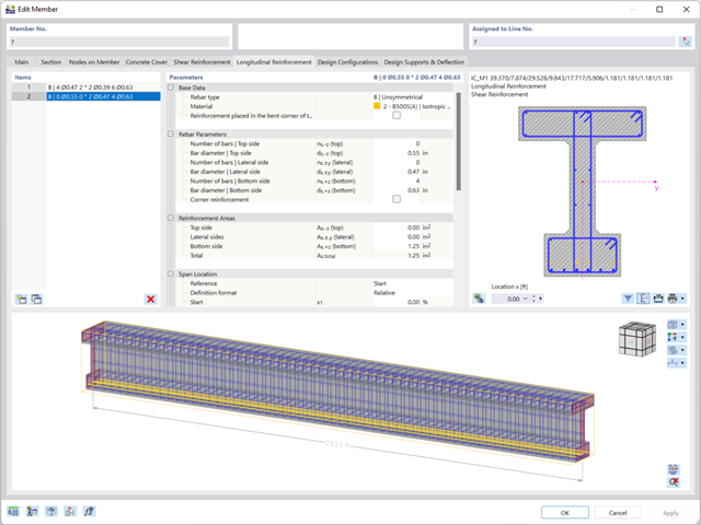
Zbrojenie na ścinanie i zbrojenie podłużne można zdefiniować indywidualnie dla każdego pręta. W tym przypadku dostępne są różne szablony do wprowadzania zbrojenia.
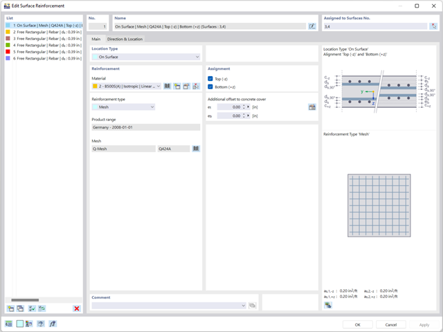
Zbrojenie powierzchniowe należy wprowadzić bezpośrednio na poziomie programu RFEM. W takim przypadku można indywidualnie wybrać zdefiniowane zbrojenie powierzchniowe. Podczas wprowadzania zbrojenia powierzchniowego do dyspozycji użytkownika są standardowe funkcje Kopiuj, Odbij lub Obróć.
.png?mw=640&hash=3c928fddb4215c3df06e0b731d5c3f2e475cd9db)
W ramach jednego pręta można zdefiniować szerokość integracyjną i efektywną szerokość płyty belek teowych (żeber) o różnych szerokościach. Pręt jest podzielony na segmenty. Przejście między różnymi szerokościami półek można sortować lub określać liniowo. Ponadto program umożliwia uwzględnienie zdefiniowanego zbrojenia powierzchni jako zbrojenia pasa przy wymiarowaniu żebra w betonie zbrojonym.
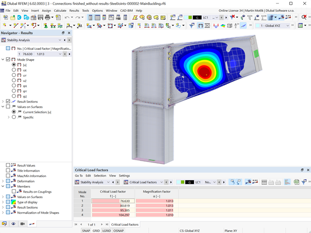
W przypadku elementów połączenia można sprawdzić, czy utrata stateczności jest istotna. Wymaga to rozszerzenia Stateczność konstrukcji.
Współczynnik obciążenia krytycznego obliczany jest dla wszystkich analizowanych kombinacji obciążeń oraz wybranej liczby postaci własnych dla modelu połączenia. Porównaj najmniejszy współczynnik obciążenia krytycznego z wartością graniczną 15 z normy EN 1993-1-1, rozdz. 5. Ponadto użytkownik może samodzielnie dostosować wartość graniczną. Wynikiem analizy stateczności jest wyświetlenie w programie graficznej postaci odpowiednich postaci drgań.
Na potrzeby analizy stateczności dostosowany model powierzchniowy jest wykorzystywany w programie RFEM do rozpoznania lokalnych kształtów wyboczeniowych. Można również zapisać model analizy stateczności wraz z wynikami i wykorzystać jako osobny plik modelu.
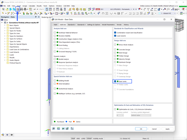
Aby zwymiarować połączenie stalowe, należy aktywować rozszerzenie Połączenia stalowe. Rozszerzenia w programie RFEM 6 są aktywowane w zakładce Rozszerzenia w oknie Edytować model - dane podstawowe. Jeżeli rozszerzenie jest aktywne, jest wyświetlane w nawigatorze.
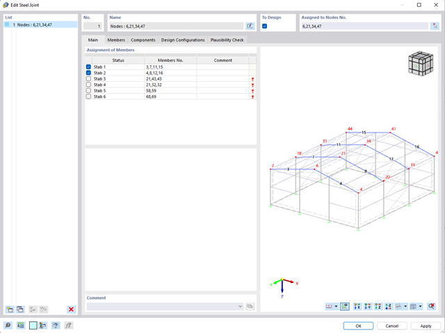
- W przypadku nowego modelu połączenia należy wybrać węzeł w modelu RFEM
- Po wybraniu węzła pręty połączone z węzłem są automatycznie rozpoznawane i przydzielane
- W oknie służącym do przydzielania prętów należy wybrać pręty, które zostaną przydzielone do połączenia
- Zaznaczone przez nas pręty są wyświetlane w oknie podglądu po prawej stronie
- Połączenia mogą być modelowane dla wielu węzłów w konstrukcji.
- Jako ustawienia prętów należy wybrać te, które mają być podparte
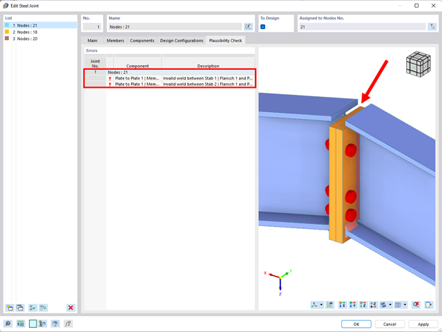
- Równolegle do wprowadzania danych program przeprowadza kontrolę poprawności, aby szybko wykryć brakujące dane wejściowe lub kolizje.
- W przypadku błędu pojawia się komunikat opisujący problem.
- Model połączeń stalowych i wyniki można zapisać jako osobny plik modelu
- Uzyskane naprężenia i wyniki analizy stateczności (wyboczenia połączenia) można wyświetlić w osobnym modelu
- W zapisanym modelu można uruchomić animację deformacji połączenia
- Elementy połączenia są podczas zapisywania przekształcane w powierzchnie i pręty
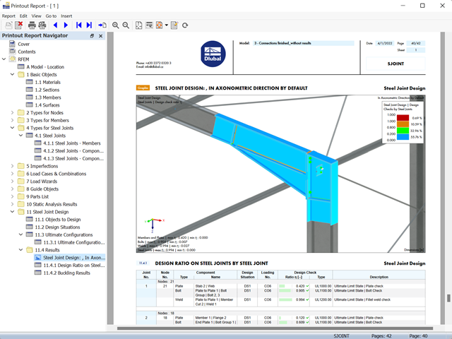
- Wyniki wymiarowania połączeń można wprowadzić do protokołu wydruku
- Podczas tworzenia nowego protokołu wydruku należy wybrać elementy dodane z rozszerzenia Połączenia stalowe
- Za pomocą narzędzia 'Drukowanie grafik do protokołu' można wstawić do protokołu grafikę z wynikami połączenia, w tym z panelem sterowania.
- Protokół wydruku zawiera specyfikacje elementów połączenia, parametry obliczeniowe, wyniki i grafiki

- Proponowane połączenie można zastosować do wszystkich wybranych węzłów w konstrukcji
- Położenie połączenia można zdefiniować w zakładce 'Główne' okna dialogowego rozszerzenia
- Obliczenia są przeprowadzane dla wszystkich połączeń w konstrukcji, a po zakończeniu obliczeń wyniki mogą być wyświetlane we wszystkich połączeniach
- W tabeli wyświetlane są wyniki dla poszczególnych połączeń, każde połączenie jest obliczane i może być zapisane osobno