97 Wyniki
Wyświetl wyniki:
Sortuj według:

W rozszerzeniu Projektowanie konstrukcji betonowych dla programu RFEM 6 można przeprowadzić obliczenia odporności ogniowej ścian i płyt żelbetowych zgodnie z uproszczoną metodą tabelaryczną (EN 1992-1-2, rozdział 5.4.2 oraz tabele 5.8 i 5.9).

- 002691
- Ogólne informacje
- Projektowanie konstrukcji betonowych RFEM 6
- Projektowanie konstrukcji betonowych RSTAB 9
W rozszerzeniu Projektowanie konstrukcji betonowych można przeprowadzić uproszczone obliczenia odporności ogniowej słupów (Rozdział 5.3.2) i belek (Rozdział 5.6), zgodnie z EN 1992-1-2.
W przypadku uproszczonych obliczeń odporności ogniowej dostępne są następujące metody weryfikacji:
- Słupy: Minimalne wymiary przekroju prostokątnego i okrągłego wg tabeli 5.2a oraz równania 5.7 do obliczania czasu ekspozycji pożarowej
- Belki: Minimalne wymiary i odległości między środkami zgodnie z Tabelą 5.5 i Tabelą 5.6
Siły wewnętrzne do obliczeń odporności ogniowej można wyznaczyć przy użyciu dwóch metod.
- 1: W tym przypadku siły wewnętrzne z wyjątkowej sytuacji obliczeniowej są bezpośrednio uwzględniane w obliczeniach.
- 2: Siły wewnętrzne z obliczeń w temperaturze normalnej są redukowane za pomocą współczynnika Eta,fi (ηfi) i są następnie wykorzystywane do obliczeń odporności ogniowej.
Ponadto istnieje możliwość modyfikacji rozstawu osi zgodnie z równ. 5.5.

Rozszerzenie Projektowanie konstrukcji betonowych umożliwia wymiarowanie prętów i powierzchni ze względu na zmęczenie zgodnie z EN 1992-1-1, rozdział 6.8.
W przypadku obliczeń zmęczenia można opcjonalnie wybrać dwie metody lub poziomy obliczeniowe w konfiguracjach obliczeniowych:
- Poziom obliczeniowy 1: Obliczenia uproszczone wg. do 6.8.6 i 6.8.7(2) Kryterium uproszczone jest stosowane dla częstych kombinacji oddziaływań zgodnie z EN 1992-1-1, rozdział 6.8.6 (2) oraz EN 1990, równ. (6.15b) wraz z obciążeniami od ruchu drogowego w stanie użytkowalności. Dla stali zbrojeniowej sprawdzany jest maksymalny zakres naprężeń zgodnie z 6.8.6. Naprężenie ściskające w betonie jest określane za pomocą górnego i dolnego dopuszczalnego naprężenia zgodnie z 6.8.7(2).
- Poziom analizy 2: Obliczanie równoważnego naprężenia niszczącego zgodnie z 6.8.5 i 6.8.7(1) (uproszczone obliczenia na zmęczenie): Obliczenia z wykorzystaniem zakresów równoważnych naprężeń niszczących są przeprowadzane dla kombinacji zmęczeniowych, zgodnie z EN 1992-1-1, rozdział 6.8.3, równ. (6.69) o specyficznie zdefiniowanym oddziaływaniu cyklicznym Qfat .

W rozszerzeniu Projektowanie konstrukcji betonowych można przeprowadzać obliczenia sejsmiczne dla prętów żelbetowych zgodnie z EC 8. Są to między innymi następujące funkcje:
- Konfiguracje obliczeń sejsmicznych
- Rozróżnianie klas ciągliwości DCL, DCM, DCH
- Możliwość przeniesienia współczynnika odpowiedzi z analizy dynamicznej
- Sprawdzenie wartości granicznej współczynnika odpowiedzi
- Weryfikacja nośności dla "Wytrzymały słup - słaba belka"
- Uszczegółowienie i reguły szczególne dla współczynnika ciągliwości krzywizny
- Uszczegółowienie i reguły szczególne dla ciągliwości lokalnej

Teraz w rozszerzeniu Projektowanie konstrukcji betonowych można wymiarować elementy wykonane z betonu zbrojonego włóknami zgodnie z wytyczną "DAfStb Steel Fiber-Reinforced Concrete".
Ta opcja jest dostępna dla obliczeń zgodnie z EN 1992-1-1. Obliczenia zgodnie z wytyczną DAfStb są przeprowadzane po przypisaniu betonu typu "Fibrobeton" do elementu konstrukcyjnego z betonu zbrojonego.
Przejdź do filmu
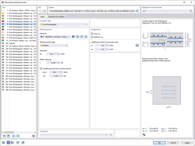
W zakładce "Zbrojenie na ścinanie" można wybrać opcję "Powiązania krzyżowe na wolnych prętach zbrojeniowych z aktywnym wyborem w oknie graficznym". Pozwala to na umieszczenie dodatkowych powiązań krzyżowych na wolnych prętach zbrojenia podłużnego.
Pozycję więzów krzyżowych można aktywować lub dezaktywować w infografice. Powiązania krzyżowe są uwzględniane podczas kontroli stanu granicznego nośności i obliczeń konstrukcji. Są one dostępne dla obliczeń zgodnie z EN 1992-1-1.
Przejdź do filmu
Wymiarowanie prętów stalowych formowanych na zimno zgodnie z AISI S100-16/CSA S136-16 jest dostępne w RFEM 6. Dostęp do obliczeń można uzyskać, wybierając normy „AISC 360” lub „CSA S16” w rozszerzeniu Projektowanie konstrukcji stalowych. Następnie dla obliczeń elementów formowanych na zimno automatycznie wybierane jest „AISI S100” lub „CSA S136”.
Do obliczania sprężystego obciążenia wyboczeniowego pręta program RFEM stosuje metodę DSM. Bezpośrednia metoda wytrzymałości oferuje dwa typy rozwiązań, numeryczne (metoda pasm skończonych) i analityczne (specyfikacja). Krzywą charakterystyczną (sygnaturę) FSM i kształty wyboczenia można wyświetlić w oknie dialogowym Przekroje.

- 002469
- Ogólne informacje
- Projektowanie konstrukcji betonowych RFEM 6
- Projektowanie konstrukcji betonowych RSTAB 9
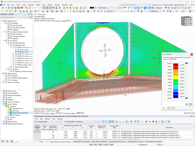
Pracujesz z elementami konstrukcyjnymi składającymi się z płyt? W takim przypadku należy przeprowadzić obliczenia na ścinanie z uwzględnieniem wymagań obliczania przebicia, na przykład zgodnie z 6.4, EN 1992-1-1. Oprócz płyt stropowych można w ten sposób wymiarować również płyty fundamentowe.
W konfiguracji stanu granicznego nośności dla wymiarowania betonu można zdefiniować parametry obliczeń przebicia dla wybranych węzłów.

- 002457
- Ogólne informacje
- Projektowanie konstrukcji aluminiowych RFEM 6
- Projektowanie konstrukcji aluminiowych RSTAB 9
Rozszerzenie Projektowanie konstrukcji aluminiowych oferuje dodatkowe opcje. W tym miejscu można również obliczać przekroje ogólne, które nie są wstępnie zdefiniowane w bibliotece przekrojów. Na przykład, utwórz przekrój w programie RSECTION, a następnie zaimportuj go do RFEM/RSTAB. W zależności od zastosowanej normy projektowej dostępne są różne formaty obliczeń. Obejmuje to na przykład równoważną analizę naprężeń.
Ist zudem eine Lizenz für RSECTION und „Effektive Querschnitte“ vorhanden, so können Sie die Nachweise auch unter Berücksichtigung der effektiven Querschnittswerte nach EN 1999-1-1 führen.

- 002458
- Ogólne informacje
- Projektowanie konstrukcji aluminiowych RFEM 6
- Projektowanie konstrukcji aluminiowych RSTAB 9
Wiesz na pewno, że podczas łączenia elementów rozciąganych za pomocą połączeń śrubowych należy wziąć pod uwagę osłabienie przekroju spowodowane otworami na śruby. Programy do analizy statyczno-wytrzymałościowej również mają na to rozwiązanie. W rozszerzeniu Aluminium Design można wprowadzić lokalną redukcję przekroju pręta. Redukcję przekroju należy wprowadzić jako wartość bezwzględną lub jako procent powierzchni całkowitej.

- 002462
- Ogólne informacje
- Projektowanie konstrukcji aluminiowych RFEM 6
- Projektowanie konstrukcji aluminiowych RSTAB 9
Czy do określenia współczynnika obciążenia krytycznego w ramach analizy stateczności użyto dodatkowego solwera wewnętrznych wartości własnych? W takim przypadku można następnie wyświetlić kształt wzorca projektowanego obiektu.

- 002451
- Ogólne informacje
- Projektowanie konstrukcji aluminiowych RFEM 6
- Projektowanie konstrukcji aluminiowych RSTAB 9
- Obliczanie ugięć i porównanie z normatywnymi lub ręcznie dostosowanymi wartościami granicznymi
- Uwzględnienie wygięcia wstępnego w analizie ugięcia
- W zależności od typu sytuacji obliczeniowej możliwe są różne wartości graniczne
- Ręczne dostosowywanie długości odniesienia i segmentacji według kierunku
- Obliczenia ugięć w odniesieniu do konstrukcji wyjściowej lub konstrukcji odkształconej
- Dalsze szczegółowe weryfikacje w zależności od wybranej normy obliczeniowej (np. weryfikacja drgań zgodnie z EN 1999-1-1, 7.2.3)
- Graficzne wyświetlanie wyników zintegrowane w programie RFEM/RSTAB, na przykład stopień wykorzystania wartości granicznej, odkształcenie lub ugięcie
- Pełna integracja wyników z raportem RFEM/RSTAB

- 002452
- Ogólne informacje
- Projektowanie konstrukcji aluminiowych RFEM 6
- Projektowanie konstrukcji aluminiowych RSTAB 9
Program wykonuje za Ciebie dużo pracy. Na przykład kombinacje obciążeń lub wyników, które są niezbędne dla stanu granicznego użytkowalności, są generowane i obliczane w programie RFEM/RSTAB. Te sytuacje obliczeniowe można wybrać w rozszerzeniu Aluminium Design w celu przeprowadzenia analizy ugięcia. W zależności od wprowadzonej przechyłki i wybranego układu odniesienia program określa obliczone wartości deformacji w każdym punkcie pręta. Następnie są one porównywane z wartościami granicznymi.
W konfiguracji Stan graniczny użytkowalności można ustawić wartość graniczną, która ma być obserwowana dla odkształcenia dla każdego komponentu z osobna. Jako dopuszczalną wartość graniczną definiuje się maksymalne odkształcenie w zależności od długości odniesienia. Definiując podpory obliczeniowe, można segmentować komponenty. W ten sposób można automatycznie określić odpowiednią długość odniesienia dla każdego kierunku obliczeń.
To nie wszystko. W oparciu o położenie przypisanych podpór obliczeniowych program automatycznie umożliwia rozróżnienie belek i belek wspornikowych. W ten sposób określana jest odpowiednio wartość graniczna.

- 002453
- Ogólne informacje
- Projektowanie konstrukcji aluminiowych RFEM 6
- Projektowanie konstrukcji aluminiowych RSTAB 9
Obliczenia w stanie granicznym użytkowalności można znaleźć w tabelach wyników w rozszerzeniu do obliczeń dla aluminium. Są tam już w pełni zintegrowane. Istnieje możliwość uzyskania wyników obliczeń w każdym punkcie wymiarowanych prętów ze wszystkimi szczegółami. Można również użyć grafiki z wynikami współczynników obliczeniowych.
W razie potrzeby wszystkie tabele wyników i grafiki można uwzględnić jako część wyników obliczeń aluminium w globalnym raporcie wydruku programu RFEM/RSTAB. Program RFEM/RSTAB umożliwia również wyświetlanie i dokumentowanie wartości deformacji całej konstrukcji niezależnie od tego, czy jest to moduł dodatkowy.

- 002454
- Ogólne informacje
- Projektowanie konstrukcji aluminiowych RFEM 6
- Projektowanie konstrukcji aluminiowych RSTAB 9
Czy bardzo to lubisz? My też! Z tego powodu wszystkie sprawdzenia dotyczące normy projektowej są wyświetlane w przejrzysty sposób. Dla każdej kontroli obliczeń należy zdefiniować kryterium wykorzystania. Szczegóły obliczeń, w których wartości wejściowe, wyniki pośrednie i wyniki końcowe są uporządkowane w sposób uporządkowany, są dostępne dla każdej kontroli obliczeń. Proces obliczeń wraz ze wszystkimi wzorami, normami i wynikami znajduje się w oknie informacyjnym, w którym wyświetlane są szczegóły obliczeń.
- 002455
- Ogólne informacje
- Projektowanie konstrukcji aluminiowych RFEM 6
- Projektowanie konstrukcji aluminiowych RSTAB 9
Weryfikacje można znaleźć w rozszerzeniu dotyczącym konstrukcji aluminiowych w postaci przejrzystych tabel. Można również przedstawić graficznie rozwój współczynników obliczeniowych. Rozbudowane opcje filtrowania są dostępne zarówno w tabeli, jak i w danych wyjściowych graficznych. W ten sposób program może wyświetlać żądane obliczenia według stanu granicznego lub typu obliczeniowego.
- 002456
- Ogólne informacje
- Projektowanie konstrukcji aluminiowych RFEM 6
- Projektowanie konstrukcji aluminiowych RSTAB 9
Przy obliczaniu granicznego ugięcia należy wziąć pod uwagę określone długości odniesienia. Te długości odniesienia i sprawdzane segmenty można definiować niezależnie od siebie, w zależności od kierunku. W tym celu należy zdefiniować podpory obliczeniowe w węzłach pośrednich pręta i przypisać je do odpowiedniego kierunku dla analizy deformacji. Tworzy to segmenty, w których można uwzględnić przechyłkę dla każdego kierunku i segmentu.

- 002460
- Ogólne informacje
- Projektowanie konstrukcji aluminiowych RFEM 6
- Projektowanie konstrukcji aluminiowych RSTAB 9
Należy upewnić się, że zdefiniowanie długości efektywnych w aluminiowym module dodatkowym jest warunkiem niezbędnym do przeprowadzenia analizy stateczności. W tym celu w oknie dialogowym należy zdefiniować podpory węzłowe i współczynniki długości efektywnej. Czy chcesz przejrzyście udokumentować podpory węzłowe i wynikające z nich segmenty wraz z powiązanym współczynnikiem długości efektywnej? W celu sprawdzenia wprowadzonych danych najlepiej jest użyć prezentacji graficznej w oknie roboczym programu RFEM/RSTAB. Oznacza to, że możesz zrozumieć projekt w dowolnym momencie i bez większego wysiłku.

- 002464
- Wyniki
- Projektowanie konstrukcji aluminiowych RFEM 6
- Projektowanie konstrukcji aluminiowych RSTAB 9
Jak zwykle, wprowadzasz układ i obliczasz siły wewnętrzne w programach RFEM i RSTAB. Masz nieograniczony dostęp do obszernych bibliotek materiałów i przekrojów. Czy wiesz, że za pomocą programu RSECTION można tworzyć przekroje ogólne? Oszczędza to dużo pracy.
Nie bój się'dodatkowych okien i chaosu przy wprowadzaniu danych! Dzieje się tak, ponieważ wymiarowanie aluminium jest w pełni zintegrowane z programami głównymi i automatycznie uwzględnia konstrukcję oraz istniejące wyniki obliczeń. Dalsze dane wejściowe dla obliczeń aluminium, takie jak długości efektywne, redukcje przekroju lub parametry obliczeniowe, można przypisać bezpośrednio do projektowanych obiektów. W wielu miejscach programu najlepiej jest użyć funkcji [Wskaż] do wyboru grafiki - w prosty i efektywny sposób.
- 002465
- Wyniki
- Projektowanie konstrukcji aluminiowych RFEM 6
- Projektowanie konstrukcji aluminiowych RSTAB 9
Czy projekt zakończył się sukcesem? Bardzo dobrze, teraz zaczyna się część zrelaksowana. Ponieważ program przedstawia przeprowadzone weryfikacje w formie tabelarycznej. Można wyświetlić szczegółowe informacje o wszystkich wynikach. Dzięki przejrzyście przedstawionym wzorom weryfikacyjnym można bez problemu zrozumieć wyniki. W oprogramowaniu Dlubal nie występuje efekt czarnej skrzynki.
Kontrole są przeprowadzane we wszystkich istotnych punktach prętów i wyświetlane graficznie jako profil wyników. Bardziej szczegółowe grafiki można znaleźć w wynikach wyszukiwania. Obejmuje to na przykład profil naprężenia w przekroju lub kształt drgań własnych.
Wszystkie dane wejściowe i wyniki są częścią protokołu wydruku programu RFEM/RSTAB. Dla poszczególnych obliczeń można wybrać zawartość raportu i żądaną głębokość danych wyjściowych.
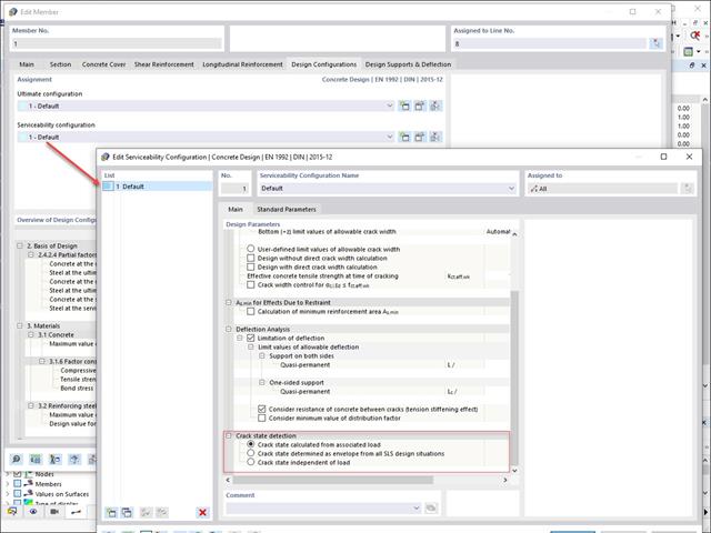
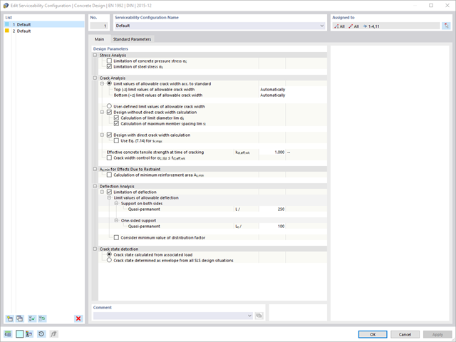
W konfiguracji stanu granicznego użytkowalności można dostosowywać różne parametry obliczeniowe przekrojów. W tym miejscu można kontrolować warunek przekroju zastosowany do analizy odkształcenia i szerokości zarysowania.
Można aktywować następujące ustawienia:
- Stan zarysowania obliczony na podstawie powiązanego obciążenia
- Stan zarysowany obliczony jako obwiednia ze wszystkich sytuacji obliczeniowych SGU
- Stan przekroju zarysowanego - niezależny od obciążenia
- Analiza deformacji powierzchni żelbetowych bez zarysowań lub z rysami (stan II) z zastosowaniem metody aproksymacyjnej (np. analiza deformacji według ACI 318-19, 24.3.2.5 lub EN 1992-1-1, kl. 7.4.3)
- Usztywnienie przy rozciąganiu betonu między rysami
- Opcjonalne uwzględnienie pełzania i skurczu
- Zintegrowane z programem RFEM graficzne przedstawienie wyników, takich jak np. odkształcenie lub ugięcie płyty płaskiej
- Przejrzyste wyświetlanie wyników numerycznych w oknie dialogowym szczegółu
- Pełna integracja wyników z protokołem wydruku programu RFEM
Szukasz obliczeń odkształceń? Należy sprawdzić konfigurację stanu granicznego użytkowalności, w której można ją aktywować. W powyższym oknie dialogowym można również kontrolować uwzględnienie efektów długotrwałych (pełzanie i skurcz) oraz usztywnienie przy rozciąganiu między rysami. Współczynnik pełzania i odkształcenie skurczowe są obliczane przy użyciu określonych parametrów wejściowych lub można je zdefiniować indywidualnie.
Ponadto można określić wartość graniczną deformacji osobno dla każdego elementu konstrukcyjnego. Maksymalna odkształcenie jest definiowane jako dopuszczalna wartość graniczna. Dodatkowo należy określić, czy do kontroli obliczeń ma zostać użyty układ nieodkształcony czy odkształcony.
Normy określają już metody aproksymacyjne (na przykład obliczanie deformacji zgodnie z EN 1992-1-1, 7.4.3 lub ACI 318-19, 24.3.2.5), które są potrzebne do obliczania deformacji. Sztywności efektywne są obliczane w elementach skończonych zgodnie z istniejącym stanem granicznym z/bez zarysowań. Sztywności te można następnie wykorzystać do określenia odkształceń za pomocą innych obliczeń MES.
Uwzględnij przekrój żelbetowy do obliczeń sztywności efektywnych elementów skończonych. Na podstawie sił wewnętrznych określonych dla stanu granicznego użytkowalności w programie RFEM, można sklasyfikować przekrój żelbetowy jako "zarysowany" lub "niezarysowany". Czy uwzględniasz wpływ betonu między rysami? W tym przypadku jest to określane za pomocą współczynnika rozkładu (np. zgodnie z EN 1992-1-1, Równ. 7.19 lub ACI 318-19, 24.3.2.5). Można założyć, że zachowanie materiału w strefie ściskania i rozciągania betonu jest liniowo-sprężyste, aż do osiągnięcia wytrzymałości betonu na rozciąganie. Procedura ta jest wystarczająco precyzyjna dla stanu granicznego użytkowalności.
Podczas określania sztywności efektywnych można uwzględnić pełzanie i skurcz na „poziomie przekroju”. W tej metodzie aproksymacji nie trzeba uwzględniać wpływu skurczu i pełzania w układach statycznie niewyznaczalnych (np. siły rozciągające od odkształceń spowodowanych skurczem w układach stężonych ze wszystkich stron nie są określane i należy je uwzględnić osobno). Podsumowując, obliczenia deformacji przeprowadzane są w dwóch krokach:
- Obliczanie sztywności efektywnych przekroju żelbetowego przy założeniu warunków liniowo-sprężystych
- Obliczanie odkształcenia przy użyciu sztywności efektywnych za pomocą MES
Czy obliczenia zostały przeprowadzone pomyślnie? Wyniki analizy odkształceń są teraz wyświetlane w przejrzyście ułożonych tabelach wyników lub w szczegółowych oknach dialogowych z tekstem informacyjnym. Program wyświetla w zrozumiały sposób wszystkie wartości pośrednie. Graficzne przedstawienie stopni wykorzystania i odkształceń w programie RFEM umożliwia szybki przegląd obszarów krytycznych.
Dzięki wynikom kontroli obliczeń wraz z wszystkimi wynikami pośrednimi można śledzić obliczenia aż do najmniejszego szczegółu. Dzięki pełnej integracji wyników w protokole wydruku programu RFEM, użytkownik otrzymuje weryfikowalne obliczenia konstrukcyjne.
- Automatyczny import sił wewnętrznych z programu RFEM/RSTAB
- Sprawdzenie stanu granicznego nośności i użytkowalności
- Wartości graniczne i parametry zdefiniowane przez użytkownika mogą być również przyjęte na podstawie zintegrowanych załączników krajowych (NA).
- Elastyczność dzięki szczegółowym opcjom ustawień dla podstawy i zakresu obliczeń
- Szybkie i przejrzyste wyświetlanie wyników dla globalnej oceny ich rozkładu na konstrukcji po zakończeniu obliczeń
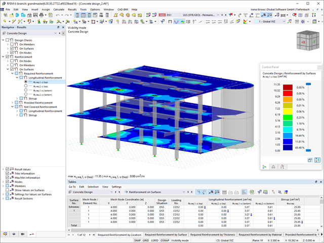
- Zintegrowane z programem RFEM/RSTAB graficzne środowisko przedstawiania wyników, np. wyświetlanie stopni wykorzystania lub wymaganego zbrojenia
- Przejrzyste zestawienie wyników w formie numerycznej w stosownych oknach oraz możliwość ich graficznego przedstawienia na konstrukcji
- Integracja wyników z protokołem wydruku programu RFEM/RSTAB
- Wyznaczanie zbrojenia podłużnego, na ścinanie i skręcanie
- Określanie zbrojenia minimalnego i ściskanego
- Określanie położenia osi obojętnej, odkształceń betonu oraz stali w przekroju
- Wymiarowanie przekrojów obciążonych momentem zginającym w dwóch kierunkach (My,Mz)
- Wymiarowanie prętów o przekrojach zbieżnych
- Wymiarowanie przekrojów RSECTION w rozszerzeniu Projektowanie konstrukcji betonowych
- Wyznaczanie odkształcenia w stanie II; na przykład zgodnie z EN 1992‑1‑1, 7.4.3 i ACI 318‑19 24.2.3, Tabela 24.2.3.5
- Uwzględnienie usztywnienia przy rozciąganiu
- Uwzględnienie pełzania i skurczu
- Projektowanie ze względu na zmęczenie, zgodnie z EN 1992-1-1, rozdział 6.8
- Uproszczone obliczenia odporności ogniowej słupów (rozdział 5.3.2) i belek (rozdział 5.6) zgodnie z EN 1992-1-2
- Obliczenia sejsmiczne zgodnie z EC 8 dla prętów żelbetowych
- Szczegółowe informacje o przyczynach nieudanych obliczeń podczas wymiarowania
- Szczegóły dotyczący wymiarowania dostępne we wszystkich kluczowych lokalizacjach na elemencie aby lepiej śledzić wyznaczanie zbrojenia
- Możliwość optymalizacji przekroju
- Wizualizacja przekroju betonowego wraz ze zbrojeniem w postaci renderu 3D
- Tworzenie wykresów interakcji w przestrzeni 2D, np. wykresu M-N
- Wizualizacja nośności przekroju na wykresie interakcji 3D
- Generowanie wykresu moment-krzywizna
- Dowolne definiowanie zbrojenia w dwóch warstwach
- Alternatywne procedury przy wymiarowaniu dzięki którym można uniknąć zbrojenia na ściskanie lub ścinanie
- Wymiarowanie powierzchni jako belek-ścian (teoria membranowa)
- Możliwość definiowania zbrojenia podstawowego dla górnej i dolnej warstwy zbrojenia
- Dowolne definiowanie istniejącego zbrojenia w powierzchni
- Wyniki są prezentowane w punktach dowolnie wybranej siatki
- Wymiarowanie przy użyciu momentów obliczeniowych na krawędziach słupa
- Wyznaczanie odkształcenia w stanie II; na przykład zgodnie z EN 1992‑1‑1, 7.4.3 i ACI 318‑19 24.2.3, Tabela 24.2.3.5
- Uwzględnienie usztywnienia przy rozciąganiu
- Uwzględnienie pełzania i skurczu
- Projektowanie ze względu na zmęczenie, zgodnie z EN 1992-1-1, rozdział 6.8
- Obliczenia połączenia ścinanego między środnikiem a pasem żebra
- Opcjonalne wymiarowanie czystych płyt lub ścian dla modelu 2D
- Szczegółowe informacje o przyczynach nieudanych obliczeń podczas wymiarowania
- Szczegóły dotyczący wymiarowania dostępne we wszystkich kluczowych lokalizacjach na elemencie aby lepiej śledzić wyznaczanie zbrojenia
Oprogramowanie Dlubal Software ułatwi Ci wiele etapów pracy. Tym samym powierzchnie, pręty, zbiory prętów, materiały, grubości powierzchni i przekroje zdefiniowane w programie RFEM/RSTAB są wstępnie ustawione tak, aby ułatwić wprowadzanie danych. W celu graficznego wyboru elementów w wielu miejscach programu można użyć funkcji [Wybrać]. Ponadto użytkownik ma dostęp do globalnych bibliotek materiałów i przekrojów.
Powierzchnie lub pręty można pogrupować w 'Konfiguracje', z których każda ma inne parametry obliczeniowe. W ten sposób można efektywnie obliczać różne warianty obliczeniowe, na przykład z uwzględnieniem różnych warunków brzegowych lub zmodyfikowanych przekrojów. Zdziwisz się, o ile szybciej wszystko działa z programem RFEM/RSTAB.
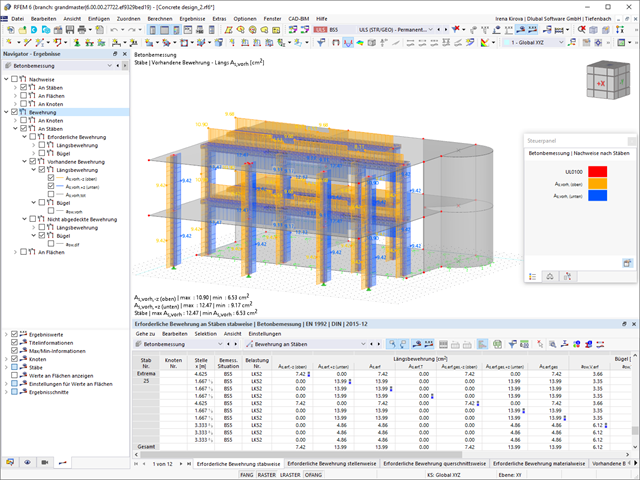
Czy obliczenia są zakończone? Następnie możesz się oprzeć. Stopnie wykorzystania poszczególnych warunków projektowych (np. stan graniczny nośności, użytkowalności lub zgodność z regułami konstrukcyjnymi) wyświetlane są w tabeli. Wymagane zbrojenie można znaleźć również w przejrzyście ułożonych tabelach wyników. Program wyświetla w zrozumiały sposób wszystkie wartości pośrednie.
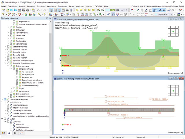
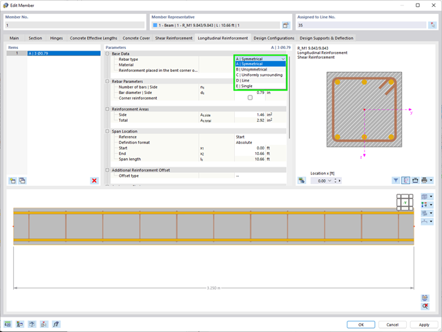
Wyniki prętów można wyświetlić w postaci wykresów wyników na odpowiednim pręcie. Ponadto istnieje możliwość udokumentowania wstawionego zbrojenia dla zbrojenia podłużnego i strzemionami, wraz z szkicami, zgodnie z aktualną praktyką.
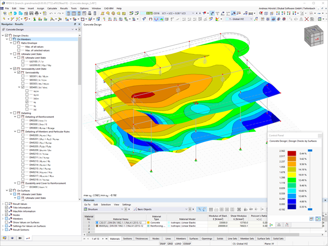
Zdecyduj, czy chcesz wyświetlić wyniki powierzchni jako izolinie, izopowierzchnie czy wartości liczbowe. Oprócz stopni wykorzystania nośności można wyświetlić zbrojenie podłużne według wymaganego, zaprojektowanego i niezapewnionego zbrojenia.