


Wind Load on Wall
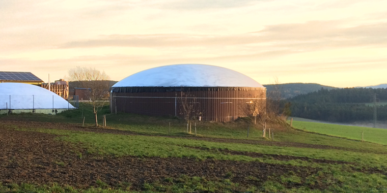
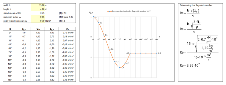
For wall surfaces, the wind loads are determined according to [1], Sect. 7.9. It describes the external pressure coefficients for circular cylinders depending on the Reynolds number, roughness, and slenderness of a surface. In the case of the warehouse shown in Image 01, the Reynolds number results in 3.35 · 107 for a velocity pressure of 0.70 kN/m². Based on [1], Figure 7.27, the external pressure coefficients for the Reynolds number of 1.00 · 107 are used by approximation. These are required in RFEM in order to define the load factor as a function of the rotation angle α.
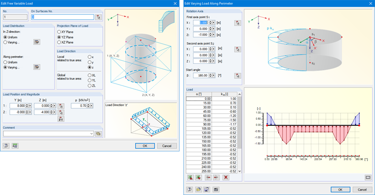
To define a load varying along the perimeter, you can use the "Free Variable Load" type, which can be found under the menu "Insert" → "Load". In the corresponding dialog box, you can select the wall surfaces first and define the projection direction. The wind acts on the local z-axis of the surface, so it is necessary to adjust the load direction accordingly. You should select the load position so that all walls are surrounded with the plane projection. As load value, the velocity pressure is defined according to [1], Sect. 4.5, or according to the national application document. Since the load along the perimeter is not constant, you can select the "Along perimeter: Varying" option. Thus, it is possible to define a load factor at any angle along the perimeter, which factorizes the load value from the previous dialog box. For factor kα, you can adopt the external pressure coefficient (cpe) for the respective angle directly. The simplest way is to prepare a document in Excel and then import the parameters using the Excel Import. Before you confirm the input, the rotation axis and the initial angle must be defined.
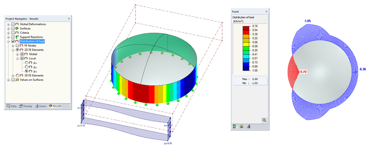
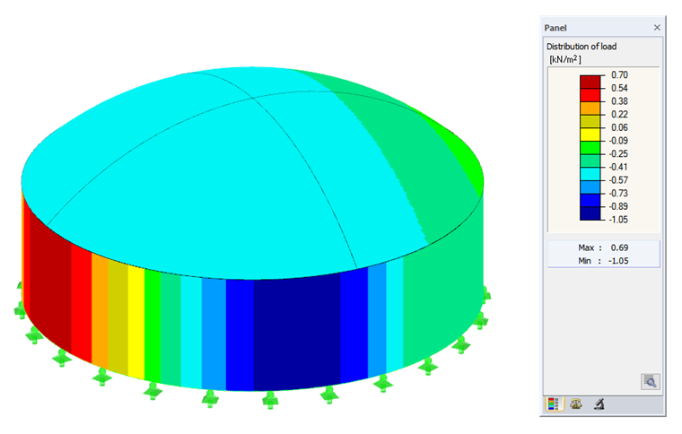
In order to check the applied loads visually, we recommend selecting the "Distribution of load" check box in the Results Navigator (see Image 04). For this control, it is sufficient to calculate an iteration for the corresponding load case. This saves time in the case of larger structures with a fine FE mesh. The accuracy of the load distribution depends on the FE mesh. The finer the FE mesh, the more accurate the load values are.
Wind Load on Dome
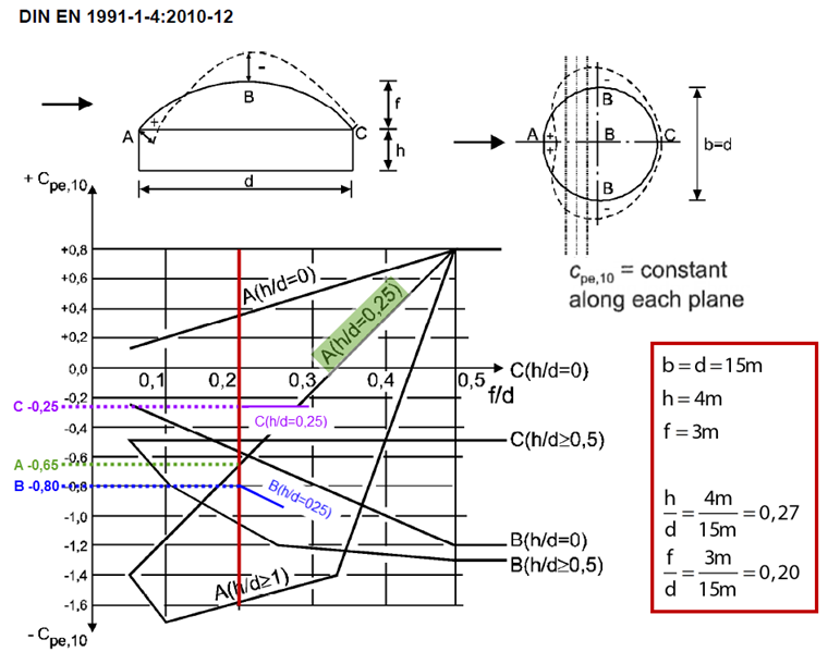
[1], Sect. 7.2.8 specifies the external pressure coefficients for domes with rectangular and circular base. In the case of the domes with circular base, the external pressure coefficients should be considered as constant along any plane perpendicular to the wind direction. As you can see in [1], Figure 7.12, the external pressure coefficients can apply to three areas (A, B, and C). The areas in between may be subjected to a linear interpolation. The external pressure coefficient has a value of -0.65 for Area A, -0.80 for Area B, and -0.25 for Area C (see Image 05). According to [1], Expression 5.1, the wind pressure result for the velocity pressure of 0.70 kN/m² is -0.46 kN/m² for Area A, -0.56 kN/m² for Area B, and -0.18 kN/m² for Area C.
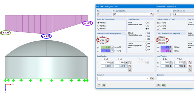
This load can be defined easily in RFEM using free rectangular loads, which can be generated in the menu "Insert" → "Loads". In addition to defining the projection plane and the load direction, it is possible to consider a linear function for the load distribution, which covers the interpolation between the individual areas as mentioned in the previous paragraph. Now, two free rectangular loads are created. One is designated for Area A to B, the second for Area B to C (see Image 06).
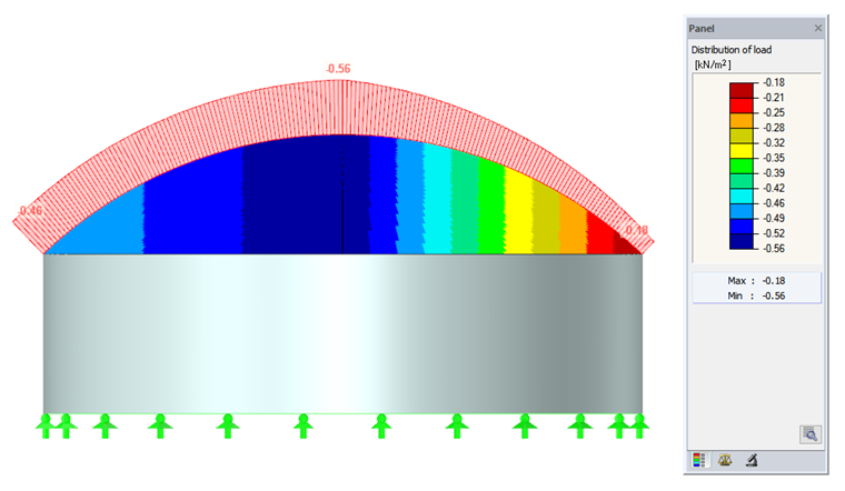
The load distribution function may help you to control the applied wind load. For a better documentation of the load effect, you can optionally create a section (see Image 07).
More Information
Domes are very sensitive to the wind load action, especially when carried out on a membrane or shell structure, and when the dome diameter is very large (for example, in the case of stadiums) [2]. In this case, it is not sufficient to consider only a wind load, but the additional stress distributions must be analyzed. Since [1] does not describe all unfavorable wind effects, the wind pressure coefficients should be verified by means of wind tunnel tests on the model. Therefore, you can also consider the effects of the dome position (for the surrounding buildings, for example).