


First of all, the roof surface geometry should only be modeled by using lines. The input of the lines is used to explain basic functions for modeling structures in RFEM 6. These can also be applied to working with members.
To create a new line, use the
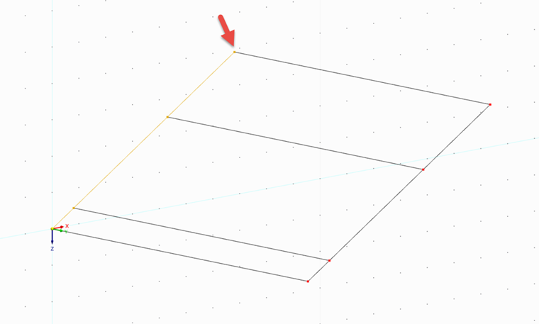
![]() button in the toolbar. First, create a line with a length of 10 m at an angle of 120° to the work plane. The angle of 120° is measured from the Z-axis, resulting in a roof inclination of 30°. Click the origin to define the start of the line.
button in the toolbar. First, create a line with a length of 10 m at an angle of 120° to the work plane. The angle of 120° is measured from the Z-axis, resulting in a roof inclination of 30°. Click the origin to define the start of the line.

Dividing Lines
You can divide a line using a specified distance by selecting the appropriate function in the shortcut menu of the line. As an alternative, you can define your own shortcut for this command. Referring to the projection in the X‑direction, the line you have just created should have the length of 6.8 m. Divide the line using this distance and delete the upper line of both newly created lines.


For the example, it should also be assumed that a ring anchor runs after a projected length of 0.8 m. After another 3.5 m, a node is also required for connecting a purlin. Create both nodes using the "Divide Line by Distance" function again.
Moving and Copying Lines
Select all lines and nodes you have created so far. These objects can be moved and copied using the
![]() button. To do this, activate the "Create copy" option and enter the vector by which the movement is to be carried out, which is by 10 m in the Y direction in this example.
button. To do this, activate the "Create copy" option and enter the vector by which the movement is to be carried out, which is by 10 m in the Y direction in this example.

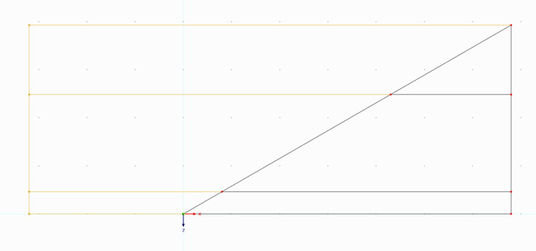
You can connect the original nodes and the copy directly with lines if you activate the step links in the "Numbering and Options" tab and select the "Link nodes with line" option in the same tab. Click "OK" to confirm, and the copy and the connecting lines will be created automatically.


Rotating Lines
You can use the
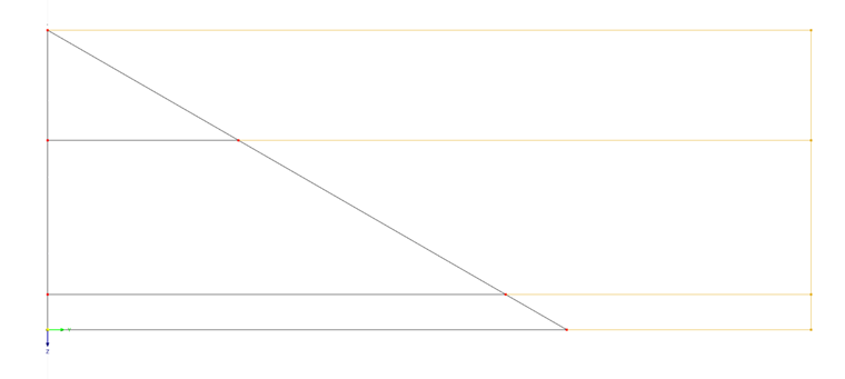
![]() button to rotate and copy the previously selected objects. This function can be used to rotate the roof edge on the left side by -90° around the Z-axis. To do this, select all associated members and nodes and open the dialog box. Activate "Create Copy", enter the angle, and select a point on the rotation axis using
button to rotate and copy the previously selected objects. This function can be used to rotate the roof edge on the left side by -90° around the Z-axis. To do this, select all associated members and nodes and open the dialog box. Activate "Create Copy", enter the angle, and select a point on the rotation axis using
![]() . In our example, this is the upper left corner node (above the origin), which will later be the edge point of the ridge.
. In our example, this is the upper left corner node (above the origin), which will later be the edge point of the ridge.

Move and copy the new objects by -10 m in the X‑direction and connect the nodes with lines again using the step link.

Connecting Lines
You can use the
![]() button to connect the selected members, lines, and surfaces at their intersections. Select all objects and then click the button to create new nodes at all intersection points of the lines.
button to connect the selected members, lines, and surfaces at their intersections. Select all objects and then click the button to create new nodes at all intersection points of the lines.
Rotate the view in order to select the unnecessary lines and delete them. For example, you can click on the -Y surfaces first, and then on the +X surface of the cube in the upper right corner of the work plane. In these views, you can easily select the lines that do not belong to the roof.
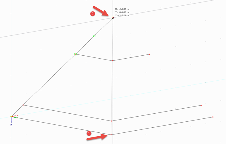
Create a new line using
![]() by clicking the bottom and top nodes of the ridge one by one. Double right-click to complete your entry. Also, delete the lines on the right side of the roof.
by clicking the bottom and top nodes of the ridge one by one. Double right-click to complete your entry. Also, delete the lines on the right side of the roof.
Mirroring Lines
Finally, the roof area created so far is to be mirrored. To do this, select all objects and use the
![]() button to open the "Mirror" dialog box. Activate "Create Copy" and select the YZ plane as the mirror plane. Use
button to open the "Mirror" dialog box. Activate "Create Copy" and select the YZ plane as the mirror plane. Use
![]() to select a point on the mirror plane; for example, the ridge point.
to select a point on the mirror plane; for example, the ridge point.

Select the nodes in the middle of the roof area and delete them by specifying in the shortcut menu of the point that the connected lines are to be connected to one another.
