


In this webinar, the load is entered using load transfer surfaces. These surfaces do not have their own stiffness, but the acting loads are distributed to the edges or integrated objects with stiffnesses.
Creating Load Transfer Surfaces
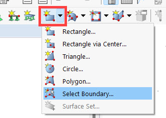
You can create a new surface by clicking the small arrow next to the
![]() button and then clicking "Select Boundary".
button and then clicking "Select Boundary".
An orthotropic load distribution is always performed using the load transfer surfaces, for which you can determine the load transfer direction. It is also possible to specify whether the load distribution is variable or constant. In the case of constant load distribution, all objects with the load distributed to them receive a constant load. Select the Load Transfer stiffness type and use the tab of the same name to specify for the example of the roof surfaces that a variable load transfer in the Y-direction is assumed.


After confirming the entry, you can select the boundary lines of the surfaces in the workspace. Create three roof surfaces in this way and double-click to close the selection.
Loads and Load Cases
In the following, loads can be applied to the surfaces that have just been created; these loads can be generated using the
![]() button. Define the load size in the self-weight load case as 1.5 kN/m² for this example.
button. Define the load size in the self-weight load case as 1.5 kN/m² for this example.

In addition to the self-weight load case, a snow load case should be considered. To do this, create a new load case in the toolbar via
![]() , deactivate the self-weight, and select the "Snow/Ice Loads" action category for an altitude below 1,000 m.
, deactivate the self-weight, and select the "Snow/Ice Loads" action category for an altitude below 1,000 m.

For this load case, create a new surface load on all three roof surfaces with a load size of 2 kN/m² in the projected Z-direction.

Load combinations
Click the
![]() button to open the "Load Cases & Combinations" dialog box. There are various tabs where you can specify the actions and load combinations to be calculated. More information about the various options can be found here:
Online Manual RFEM 6 | Load cases & combinations
.
button to open the "Load Cases & Combinations" dialog box. There are various tabs where you can specify the actions and load combinations to be calculated. More information about the various options can be found here:
Online Manual RFEM 6 | Load cases & combinations
.
In this webinar, it is sufficient to define a linear static analysis for all design checks. This can be done in the "Design Situations" tab.
