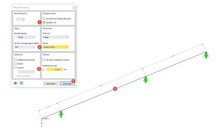
The first view to be created for the printout report relates to the geometry of the hip rafter. This requires a dimension that you can create in the toolbar using the
![]() button. Set a new dimension referring to the current coordinate system and displayed in the second plane. Then click on the members the dimensioning should refer to, and select an offset of 0.5 m. By applying the default setting, the new dimension is created.
button. Set a new dimension referring to the current coordinate system and displayed in the second plane. Then click on the members the dimensioning should refer to, and select an offset of 0.5 m. By applying the default setting, the new dimension is created.
If you want to enter horizontal or vertical dimension lines, you can use the "Projection in U" and "Projection in V" references.
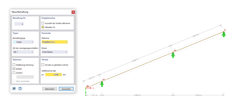
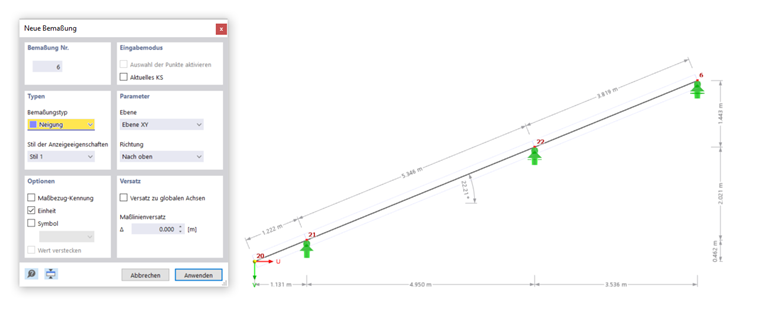
You can enter the roof inclination by creating a new dimension and selecting the "Inclination" dimension type. Click on a member of the hip rafter and drag the dimension as large as you want. Then, confirm your entry by left-clicking in the workspace.
Deactivating Dimension Guidelines
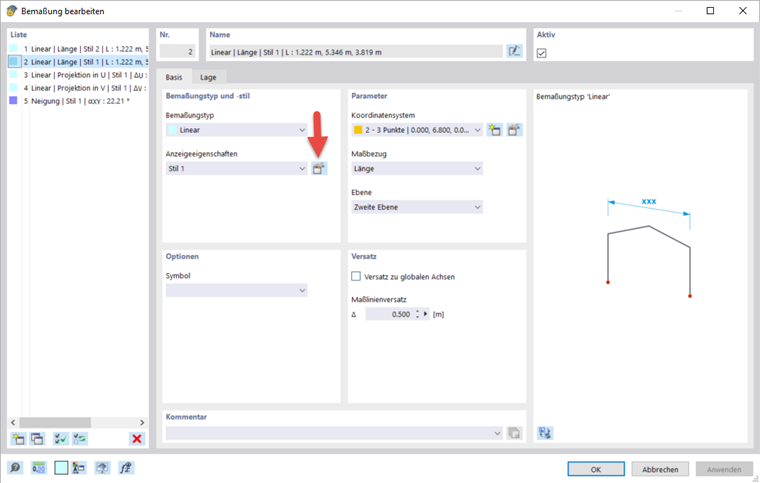
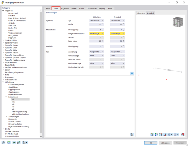
If there are guidelines displayed for the dimensions you would like to deactivate, open the "Edit Dimensions" dialog box by double-clicking the dimension. Use
![]() to go to the display settings for the dimensions. In the "Linear" and "Inclination" tabs, you can specify that the length of the dimension guidelines is defined by a fixed length and not by the offset of the dimension.
to go to the display settings for the dimensions. In the "Linear" and "Inclination" tabs, you can specify that the length of the dimension guidelines is defined by a fixed length and not by the offset of the dimension.