


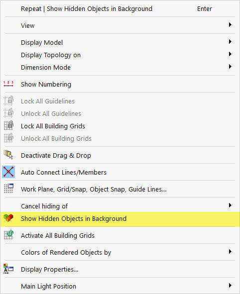
Before you start entering the design specifications, you can limit the visibility to the hip rafter.
Use the
![]() ibutton to display the objects selected at the time. You can select in the shortcut menu of the workspace whether to still see the hidden objects in the background.
ibutton to display the objects selected at the time. You can select in the shortcut menu of the workspace whether to still see the hidden objects in the background.
Creating Member Set
Since the hip rafter is to be designed as a whole, the following section shows you how to connect the individual members to create a member set.
You can quickly create a member set by selecting the relevant members using multiple selection (by window or by holding down the Ctrl key). In the shortcut menu of one of these members, select the Create Member Set function./#

Create a new member set for the three members of the hip rafter and activate the design properties. Thus, the members will not be designed individually, but rather using a member set.

Effective Lengths and Service Classes
You can make all entries relevant for the design in the additional tabs.
In the "Design Types" tab, you can specify the effective lengths for the stability analysis using the equivalent member method, as well as the timber service class. By default, all members and member sets are assigned to Service Class 1.
The following section describes how to enter new effective lengths that you can create using
![]() .
.

A dialog box appears where you can set the stability analysis to be carried out. In this webinar, the flexural buckling about the minor axis and the lateral-torsional buckling can be neglected.

The second tab, "Nodal Supports and Effective Lengths", is used to enter the nodal supports used to subdivide the member set into segments.
- banner.info@By default, there is always a lateral and torsional restraint at the start and end nodes. The nodal supports are not transferred automatically from the main model, so manual adjustment is necessary in most cases.
For the hip rafter, it is necessary to define two additional nodal supports at the support points for the peripheral ties and the purlin. To do this, activate the intermediate nodes, then add two intermediate nodes using
![]() . The program automatically finds both nodes that lie on the member set. The cantilever at the lower end of the hip rafter is not supported (3). Furthermore, no buckling should be considered (4). Click "OK" to confirm your setting. More options for entering effective lengths can be found here:
. The program automatically finds both nodes that lie on the member set. The cantilever at the lower end of the hip rafter is not supported (3). Furthermore, no buckling should be considered (4). Click "OK" to confirm your setting. More options for entering effective lengths can be found here:

In the "Design Configurations" tab, you can use
![]() to edit the design limit values of the ultimate and serviceability design checks.
to edit the design limit values of the ultimate and serviceability design checks.
Design Support
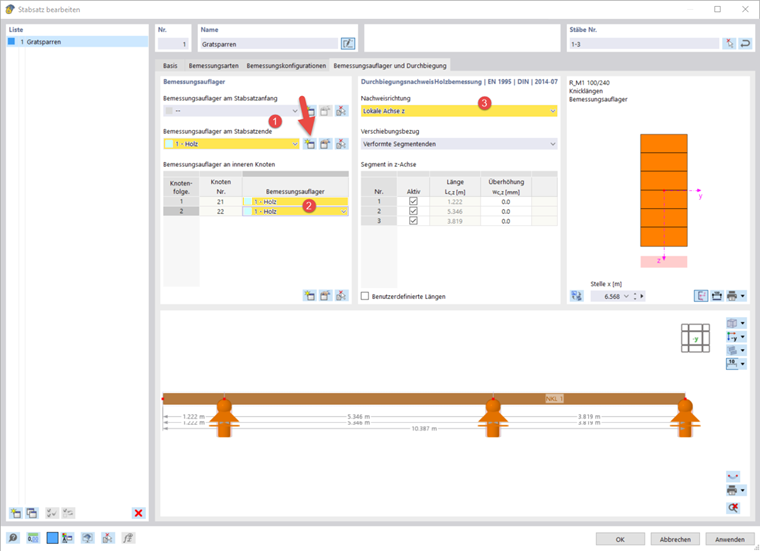
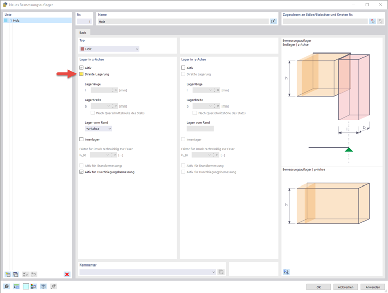
The design supports are used to define the boundary conditions for the design of "compression perpendicular to the grain" and the segmentation of the member set for the deflection analysis. You can specify them in the "Design Support and Deflection" tab. Up to now, it has not been possible to consider an inclined member, such as the hip rafter, which may be rounded or has a birdsmouth cut. In such a case, deactivate the "Direct Support" after you have created a new design support using
![]() . As an alternative, you can use the "General type". In both cases, the program does not perform the design of "compression perpendicular to the grain". Since the design supports are required for the serviceability limit state design, they still have to be defined. If you want to exclude a segment of the member set from the deflection analysis, select the "Active" option in the "Deflection Analysis" dialog box section.
. As an alternative, you can use the "General type". In both cases, the program does not perform the design of "compression perpendicular to the grain". Since the design supports are required for the serviceability limit state design, they still have to be defined. If you want to exclude a segment of the member set from the deflection analysis, select the "Active" option in the "Deflection Analysis" dialog box section.
Create a new design support as described above and assign it to the end of the member set and the intermediate nodes. Finally, you can select the design direction of the deflection analysis in the tab. In our example, it is the local one in the Z‑direction.
All entries relevant for the design have been made, and you can now start the design.