The structure for the calculation with 7 degrees of freedom is modeled using members in RFEM and RSTAB. A general explanation of the object can be found in the chapter Members of the RFEM manual. Surfaces and solid can also be included in a model with activated Torsional Warping. These objects behave in the same way as in a calculation without Torsional Warping.

Calculation of Members with 7 Degrees of Freedom
After activating the Torsional Warping (7 DOF) add-on “Beam” members are automatically calculated with 7 degrees of freedom if a cross-section with activated warping stiffness is assigned. After the calculation, additional results are displayed for these members.
The cross-section warping as the 7th degree of freedom is only considered for members of the “Beam” member type. It is necessary to activate the warping stiffness in the assigned cross-section (see the chapter Cross-Sections).
- /#
Calculation of Members with 6 Degrees of Freedom
If a cross-section with the warping stiffness deactivated is assigned to a member of the “Beam” type, this member is also calculated with 6 degrees of freedom only. The option to deactivate the warping stiffness is also described in the chapter Cross-Sections.
All members of a different member type are always calculated with 6 degrees of freedom. This restriction of the member type applies regardless of the option selected to activate warping stiffness in the cross-section.
Boundary Conditions
The boundary conditions for the 6 degrees of freedom ux, uy, uz, φx, φy, and φz are defined by specifying nodal supports.
By default, warping at the member ends is assumed to be unrestricted. Use member transverse stiffeners to define warping restraints at the member ends. These can also be used to model a warping support.
It is also possible to use member supports to define the boundary conditions.
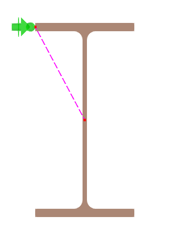
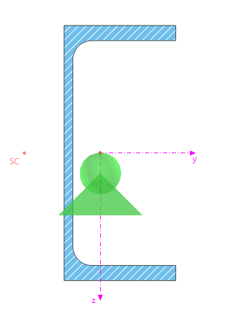
Please note that in the case of calculation with 7 degrees of freedom, all supports are applied at the center of gravity of the cross-section. Depending on the location of the shear center of the cross-section used for the member, an additional torsional moment may result. During the calculation with 6 degrees of freedom, the support for the transverse displacements uy and uz of the member is always located at the shear center. The same applies to the connection of the adjacent structural components, as explained in the section Connection Point to Adjacent Components.
Transitional Conditions
As in the case of the calculation with 6 degrees of freedom, the connection of members in a common node is assumed to be rigid. The global deformations and rotations are therefore the same at all member ends that meet at the node. Define member hinges to specify the transition conditions of the 6 degrees of freedom ux, uy, uz, φx, φy, and φz and to deviate from the rigid link. In addition to defining spring values, nonlinearities are also possible. The chapter Member Hinges of the RFEM manual describes the function of member hinges.
By default, the warping at the member ends is assumed to be unrestrained. Therefore, the bimoment and warping are not transferred to the adjacent members. You can create the continuity of warping and bimoment by modeling undivided members or by defining member sets. For more information, refer to the chapter Member Sets.

Connection Point to Adjacent Components
If other objects are connected to a member to be calculated with 7 degrees of freedom, the connecting point is always assumed to be at the center of gravity. Transverse loads from an adjacent structural component or support thus generate an additional torsional moment depending on the location of the shear center.
When calculating members with 6 degrees of freedom, however, lateral forces from other structural components are introduced at the shear center. Axial forces from other structural components are transferred at the center of gravity in both cases.
If the connection is to be made at a different point, you can model the connection with rigid members or use member eccentricities.