


The definition of member transverse stiffener allows for the specification of the boundary conditions for the warping ω when calculating members with 7 degrees of freedom. You can specify the warping stiffness at a specific location directly or have it calculated automatically for available types (see also the section Resulting Warping Restraint).

Assignment to Member or Member Set
Member transverse stiffeners are organized in RFEM and RSTAB as a "Type for Members". Thus, you can assign the member transverse stiffeners to one or more members by using the Edit Member dialog box, by selecting them in the Member Transverse Stiffener dialog box, or via the input table.
Furthermore, it is possible to assign the member transverse stiffeners to a member set. The relative position of the stiffener types refers then to the length of the entire member set. Note that a member transverse stiffeners can be assigned either to a member or to a superordinate member set.
Stiffener Type and Location
In the Stiffener Type and Position section, specify all stiffener types and their locations. Click the
![]() button to switch between the absolute and relative input of the position. Click the
button to switch between the absolute and relative input of the position. Click the
![]() button to sort the list according to the positions.
button to sort the list according to the positions.
The following types are currently available:
- Flat stiffeners
- End plates at the member start and end
- Channel sections
- Angle sections (connection of both legs to the stiffened web)
- Connecting columns at the member start and end
- Warping restraints
Depending on the cross-section of the member, there may be restrictions on the assignment of types. For general cross-sections (for example, from RSECTION), only stiffeners of the “Warping restraint” type are allowable. If you assign an incompatible stiffener type, a corresponding warning message is displayed.
Some stiffener types (such as flat stiffeners) require entering the stiffener position (left, right, or double-sided). In this case, the left side means the side lying in the negative y-direction.
Select the "Multiple" check box to add more stiffeners of the same type to a beam. In the parameters, you can now specify the number of stiffeners and the offset recurrence.
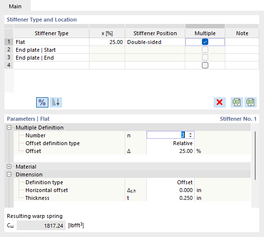
Parameters
In this section of the dialog box, you define the main properties of each stiffener type. In most cases, this requires the information about the material and dimensions of the stiffener.
If you have also activated one of the design add-ons Steel Design or Aluminum Design, the "Consider stiffener" check box is available. For more information on considering the transverse stiffeners in the design add-ons, see the relevant chapters of the add-on manuals:
Resulting Warp Spring
The resulting warp spring is calculated automatically for each type of cross-section stiffener and the given cross-section according to the entered parameters. The value is displayed in the lower dialog box section if a unique value exists for all situations. Otherwise, the maximum and minimum values are displayed in this text box (for example, when used on several members with different cross-section depths). The calculation formulas for different types of warp springs can be found in the technical article Calculation of Warping Springs for Consideration in Lateral-Torsional Buckling Analysis for Open Cross-Sections.
When specifying a user-defined warp spring, the entered stiffness is applied at the defined location. You can also select the application of a rigid warping restraint.
Calculation of Members with 6 Degrees of Freedom
When calculating members with 6 degrees of freedom, member transverse stiffeners have no impact on the system stiffness. However, you can include them in the design using the Steel Design and Aluminum Design add-ons by selecting the “Consider Stiffener” check box (see also section Parameters).