


The dialog box for member hinges corresponds to the dialog box for the calculation with 6 degrees of freedom, even when using the Torsional Warping (7 DOF) add-on. The RFEM manual describes the function of member hinges in the chapter Member Hinges. It is not possible to define a warping release here.
Transition Conditions for 6 Degrees of Freedom
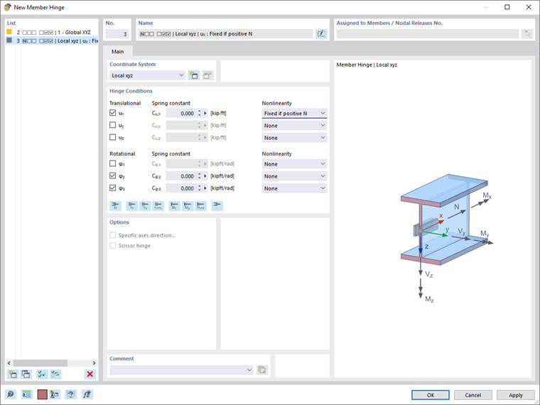
As in the case of the calculation with 6 degrees of freedom, the connection of members in a common node is assumed to be rigid. The global deformations and rotations are therefore the same at all member ends that meet at the node. Define member hinges to specify the transition conditions of the 6 degrees of freedom ux, uy, uz, φx, φy, and φz and to deviate from the rigid link. In addition to defining spring values, nonlinearities are also possible.
Transition Conditions for Warping
The warping at the member ends is assumed to be unrestricted by default. Therefore, the bimoment and warping are not transferred to the adjacent members. You can create the continuity of warping and bimoment by modeling undivided members or by defining member sets. For more information, refer to the chapter Member Sets.
You can enter warping restraints in members by defining Member Transverse Stiffener, as explained in the corresponding chapter of this manual.