


The load application point is crucial when applying forces to members, as additional moments can result from the distances to the center of gravity or shear center. The load application point is particularly important for a geometrically nonlinear calculation, as an eccentric load can increase or decrease a torsion (see also the superordinate chapter Load ).
In the following, you will find notes on the load application point for the relevant load types in a calculation with 7 degrees of freedom.
Member and Member Set Loads
If you define a member load without eccentricity, the load always acts at the center of gravity in the calculation with 7 degrees of freedom. By activating the “Eccentricity” option in the editing dialog box of a member load, you can specify the load application point yourself. The center of gravity, the shear center, and specific edge points of the cross-section are available. It is also possible to enter eccentricity values with reference to the selected point.
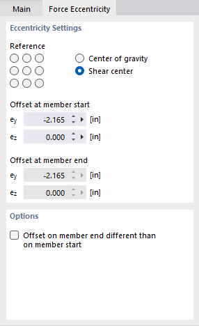
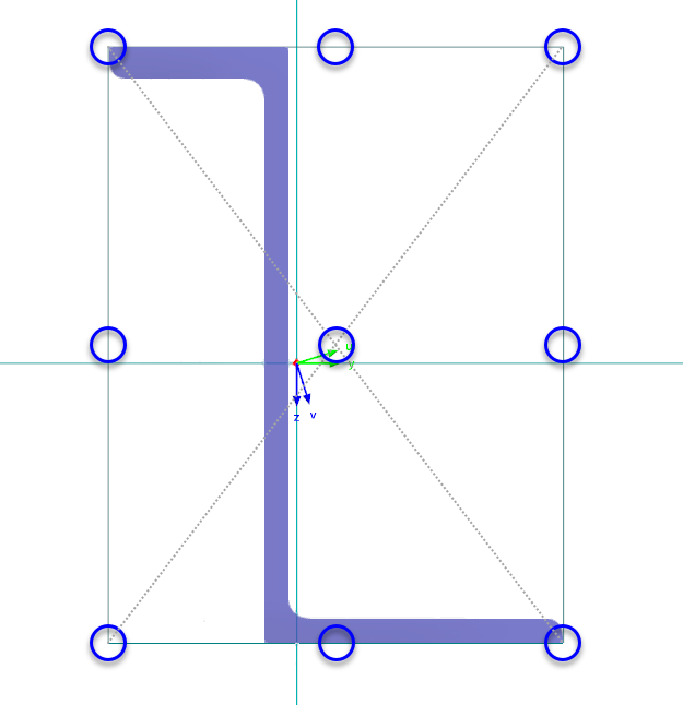
The center point represents the geometric center of a rectangle that describes the cross-section. The eight edge points are the intersection points of the parallel member axes y and z through this center with the edge lines of the rectangle. This provides you with a simple definition option for typical situations (such as the “left corner of the upper flange” on an I-section).
Nodal Loads
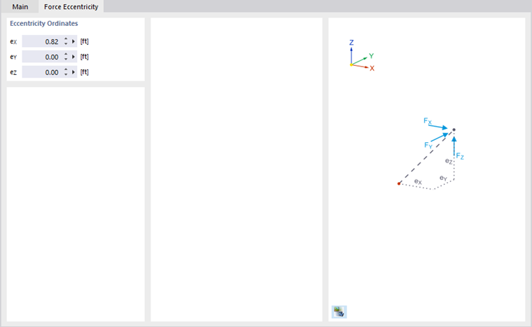
Nodal loads always refer to the location of the definition node. After activating the “Eccentricity” option in the editing dialog box, you can specify an eccentricity value for the loads for each direction of the selected reference system. You can specify the eccentricity values manually or parameterize them using formulas and calculate them from existing cross-section properties.
Load Distribution Areas
In RFEM, you can use load transfer surfaces to distribute a load acting on the surface to integrated members. Note that the load from a load transfer surface on the members is always assumed to act at the center of gravity. This also applies to members arranged eccentrically to the load application surface if they have not previously been excluded from the load distribution. It is currently not possible to take a connection eccentricity into account here.
Further information can be found in the chapter Surfaces of the RFEM manual.
Load Wizards
There are various load wizards available in RFEM and RSTAB for generating wind or snow loads. Please note that the load generated by load wizards on the members is always assumed to act in the center of gravity. This also applies to members arranged eccentrically to the load application surface if they have not previously been excluded from the load distribution. It is currently not possible to take into account a joint eccentricity.
Use the “Separate generated load” function to convert the generated loads into member loads and use the eccentricity settings described in the section Member Loads. For more information on the load wizards, please refer to the chapter Load Wizards of the RFEM manual.
Load from Adjacent Components
If other objects are connected to a member to be calculated with 7 degrees of freedom, the connecting point is always assumed to be at the center of gravity. Transverse loads from an adjacent structural component or support thus generate an additional torsional moment depending on the location of the shear center.
If the connection is to be made at a different point, you can model the connection with rigid members or use member eccentricities. Further information can be found in the chapter Members of this manual.