


The dialog box for nodal supports corresponds to the dialog box for the calculation with 6 degrees of freedom, even when using the Torsional Warping (7 DOF) add-on. The RFEM manual describes the input of nodal supports in the chapter Nodal Supports. It is not possible to define a support for warping in this case.
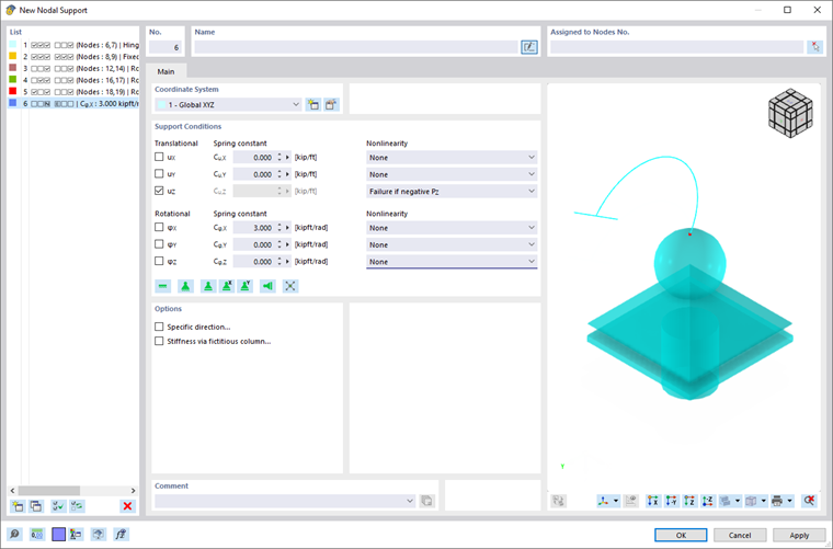
Boundary Conditions for 6 Degrees of Freedom
By defining nodal supports, you specify the boundary conditions of the 6 degrees of freedom ux, uy, uz, φx, φy, and φz at a node. In addition to defining spring values, nonlinearities are also possible.
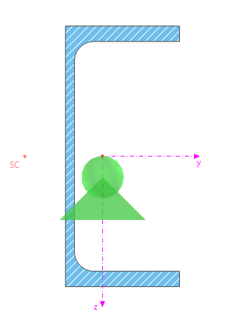
In the case of a calculation with 7 degrees of freedom, nodal supports are assumed at the center of gravity of the cross-section. Depending on the location of the shear center of the cross-section used for the member, an additional torsional moment may result. In the case of a calculation with 6 degrees of freedom, the support for the transverse displacements uy and uz of the member is always located at the shear center.
Boundary Conditions for Warping
The warping at the member ends is assumed to be unrestricted by default. Use member transverse stiffeners to define warping restraints at the member ends. These can also be used to model a warping support.
