


The dialog box for member supports corresponds to the dialog box for the calculation with 6 degrees of freedom, even when using the Torsional Warping (7 DOF) add-on. The RFEM manual describes the input of member supports in the chapter Member Supports. For the calculation with 7 degrees of freedom, the definition of fictitious stiffnesses from member shear panels and member rotational restraints is particularly relevant.
Activating Fictitious Stiffnesses for Static, Stability, and Modal Analysis
Fictitious stiffnesses from member shear panel and member rotational restraint have no effect on static, stability, and modal analysis by default. You can activate the fictitious stiffnesses for this purpose using a structure modification.
Assignment to Member or Member Set
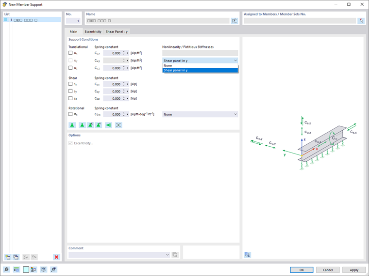
Assign a member shear panel or member rotational restraint to a member support in order to consider its stiffness in the calculation with 7 degrees of freedom. To do this, first select the fictitious stiffness "Shear Panel in y" or "Shear Panel in z" in the "Nonlinearity / Fictitious Stiffnesses" list of the "Main" tab.
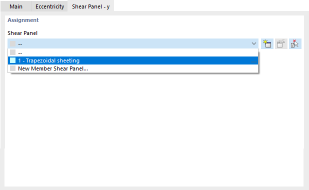
In the "Shear Panel – y" or "Shear Panel – z" tab, you can then assign the shear panel you want. The member rotational restraint is selected in the same way in the ‘“Rotational Restraint” tab.
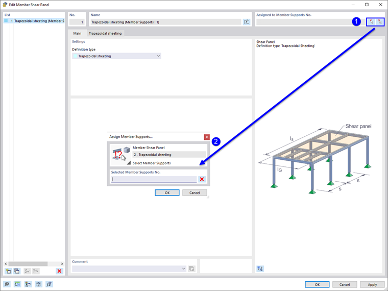
You can also assign the bar thrust field or bar member rotational restraint to a member support graphically in the editing dialog box of the member shear panel or the member rotational restraint by using the
![]() button. However, it is necessary that an object of this type is already assigned to the member support.
button. However, it is necessary that an object of this type is already assigned to the member support.
The member supports with the defined member shear panels or rotational restraints defined have to be assigned either to the members or to the superordinate member sets. Assign the member support using the editing dialog box of the member or member set, the selection from the Member Support dialog box, or using the input table.
Definition of Fictitious Stiffnesses
You can enter member shear panels and member rotational restraints using separate objects that are assigned to the member support. You will find a detailed description in the following chapters:
Location of Member Support on Cross-Section
You can define the location of the member support on a cross-section in the “Eccentricity” tab of the "Member Supports" dialog box.
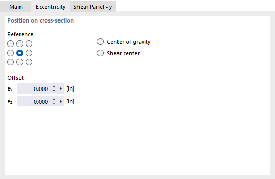
Nine "Reference" check boxes symbolize distinctive locations on the cross-section. The point in the middle represents the centroid, and the eight edge points represent the intersections of the member axes y and z with the edge lines of a rectangle circumscribing the cross-section.
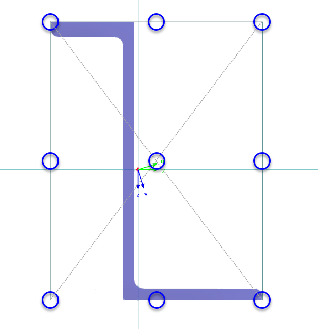
In addition to the nine check boxes, you can also use the center of gravity and the shear center as a reference point.
You can define the "offset" manually in the text boxes below. The distances are based on the position of the reference point and refer to the local member axes y and z.