Baku Flame Towers in Baku, Azerbaijan
Customer Project
Since 2012, the city of Baku, capital of Azerbaijan, has a striking complex of high-rise buildings: the Baku Flame Towers. The construction consists of three towers which have the shape of a flame with a maximum height of 190 m. The flame shape designed by HOK Architects was inspired by the importance of fire for the town, as there is a high number of oil wells in the region.
Structural Engineering |
Facade Design and Structural Analysis of Tower Spires Werner Sobek Stuttgart GmbH & Co. KG, Stuttgart, Germany www.wernersobek.de |
Architectural Design |
HOK Architects London, UK www.hok.com |
Model
The dimensions indicated below refer to one of the three spires.
Length: ~ 35 m | Width: ~ 34 m | Height: ~ 30 m
Number of nodes: 772 | Members: 981 | Finite Elements: 981 | Materials: 2 | Cross-sections: 9
The Dlubal Software customer Werner Sobek Stuttgart was responsible for the steel spires put on the towers as well as for the spectacular facade.
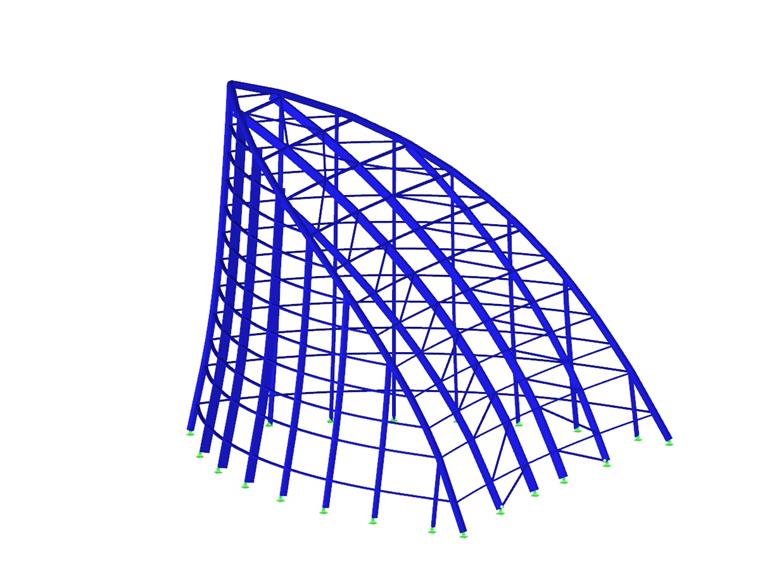
Supporting Structure of Tower Spires
The main structural systems of the three towers consist of reinforced concrete. In contrast, the towers' top stories consist of filigree steel frameworks which provide spacious room for special use.
The primary framework of the spires consists of a spatial three‑hinged frame built up of round pipes with a diameter of 610 mm. Following the given geometry, the pipes were taken as biaxially curved sections to the construction site where they were connected to each other by butt welds.
To reduce deformations of the construction that is 30 m high, the vertical side steel columns were attached to the frame by bending resistant connections. A special triangular cross‑section made of typical metal sheets and round steel bars was used for these columns to allow for an outside view that is as wide as possible. This cross‑section was modeled in the Dlubal program SHAPE‑THIN and then imported to RFEM.
The wind loads that were governing for the design were determined by a wind report, reaching very high values of 7 kN/m². Therefore, additional diagonals were needed on the curved back side of the steel constructions in order to reduce the total deformation on the tower spire to the required 90 mm.
Because technical planners were working closely together in an early phase of the project, the planning was performed successfully on schedule.
Keywords
Write Comment...
Write Comment...
Contact us
Do you have questions or need advice?
Contact our free e-mail, chat, or forum support or find various suggested solutions and useful tips on our FAQ page.

New
Displaying Temporary Analysis Models from RF-GLASS
When using the RF‑GLASS add‑on module, you can define in the main program just the geometry as well as the load situation of the structural component to be designed. The respective support conditions and all further design-relevant definitions, for example the layer structure and support conditions, can be further specified in RF‑GLASS.

SHAPE-THIN | Cold-Formed Sections
SHAPE-THIN determines the effective cross-sections according to EN 1993-1-3 and EN 1993-1-5 for cold-formed sections. You can optionally check the geometric conditions for the applicability of the standard specified in EN 1993‑1‑3, Section 5.2.
The effects of local plate buckling are considered according to the method of reduced widths and the possible buckling of stiffeners (instability) is considered for stiffened sections according to EN 1993-1-3, Section 5.5.
As an option, you can perform an iterative calculation to optimize the effective cross-section.
You can display the effective cross-sections graphically.
Read more about designing cold-formed sections with SHAPE-THIN and RF-/STEEL Cold-Formed Sections in this technical article: Design of a Thin-Walled, Cold-Formed C-Section According to EN 1993-1-3.
- Why do I get large differences for the design of a longitudinally stiffened buckling panel in comparison with the German and Austrian National Annex?
- How can I create a curved or arched section?
- How can I perform the stability analysis in RF‑/STEEL EC3 for a flat bar supported on edges, such as 100/5? Although the cross-section is rotated by 90° in RFEM/RSTAB, it is displayed as lying flat in RF‑/STEEL EC3.
- How are the signs for the release results of a line release and line hinges interpreted?
- How is the rotational stiffness of a buckling stiffener determined in PLATE‑BUCKLING?
- How are hot-dip galvanized components considered for fire resistance in the RF‑/STEEL EC3 add-on module?
- In RF‑/STEEL EC3, is the "Elastic design (also for Class 1 and Class 2 cross-sections)" option under "Details → Ultimate Limit State" considered for a stability analysis when activated?
- How can I get the member end forces to design the connections?
- I would like to calculate and design "temporary structures." What do I need for this?
- How can I create a drilled beam in RFEM?
Programs Used for Structural Analysis