Home Downloads & Info References Customer Projects Recreational Area Tension Membrane Structure in Châteauneuf-de-Galaure, France
Recreational Area Tension Membrane Structure in Châteauneuf-de-Galaure, France
Customer Project
The engineering company ACS provided the full project structural analysis and design including the fabric membrane and frame structure.
Investor | O.G.E.C Châteauneuf - Saint-Bonnet, Châteauneuf-de-Galaure, Frankreich |
Construction Management |
H2C Architecture, Lyon, France www.h2c-architecture.fr |
Structural Analysis | AC Structures, Rennes, France |
Frame Structure |
ICM, Marseille, France www.icm13.fr |
Membrane |
ACS Production, Montoir de Bretagne, France www.acs-production.com |
- Length: 131 ft
- Width: 66 ft
- Height: 27 ft
- Membrane Surface: 8267 ft²
- Weight: 31 St
Model
Description
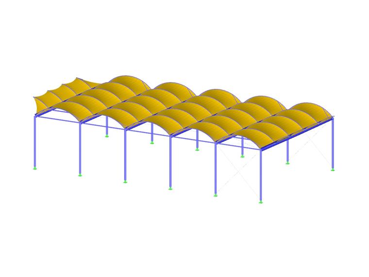
The covered recreational area consists of 6 frames with steel tube columns and welded galvanized steel I-beams covered with a double-curvature PVC membrane. The roof spans over the Foyer de Charité de Châteauneuf-de-Galaure, Drôme department school grounds.
A channel system integrated into the welded I-beams and downpipes integrated into the columns allow for unobtrusive rainwater drainage and improved aesthetic appeal.
Modeling
For the structural design, the following Dlubal Software programs were utilized: RF-STEEL EC3 add-on module for the calculation of the steel supporting structure, the RF-FORM-FINDING add-on module to determine the fabric membrane shape and determine the membrane ultimate limit state, and the RF-CUTTING-PATTERN add-on module to create the fabric cutting pattern geometry.
To begin, a general structural analysis model including the steel frame and membrane was created. The supporting steel structure was further designed taking into consideration the fabric membrane forces. Additionally, the fabric analysis and design were also carried out for the overall structure design.
In the second phase, the roof panels were separated and the fabric stress curves and changing curvatures were checked. A second, more accurate and detailed model was developed.
The modeling phases alternated with the design phases to consider the interaction of the fabric and frame.
Project Location
85 Rue Geoffroy de Moirans,26330 Châteauneuf-de-Galaure,
France
Keywords
Dlubal Software AC Structures RFEM RF-STEEL EC3 RF-FORM-FINDING RF-CUTTING-PATTERN Frame structure Membrane Find shape
Contact us
Do you have questions or need advice?
Contact our free e-mail, chat, or forum support or find various suggested solutions and useful tips on our FAQ page.
Recommended Events
Timber Beam and Surface Structures | Part 1: Modeling, Load Input, Combinatorics
Webinar 4 May 2021 2:00 PM - 3:00 PM CEST
Eurocode 3 | Steel structures according to DIN EN 1993-1-1
Online Training 6 May 2021 8:30 AM - 12:30 PM CEST
Eurocode 2 | Concrete structures according to DIN EN 1992-1-1
Online Training 12 May 2021 8:30 AM - 12:30 PM CEST
Eurocode 5 | Timber structures according to DIN EN 1995-1-1
Online Training 20 May 2021 8:30 AM - 12:30 PM CEST
RFEM | Structural dynamics and earthquake design according to EC 8
Online Training 2 June 2021 8:30 AM - 12:30 PM CEST
Stability Design in Steel Construction with RFEM and RSTAB
Webinar 1 December 2020 2:00 PM - 2:45 PM CET
Videos
Models to Download
Knowledge Base Articles

New
CSA S16:19 Stability Considerations and the New Annex O.2
Structure stability is not a new phenomenon when referring to steel design. The Canadian steel design standard CSA S16 and the most recent 2019 release is no exception.
Screenshots
Product Features Articles

SHAPE-THIN determines the effective cross-sections according to EN 1993-1-3 and EN 1993-1-5 for cold-formed sections. You can optionally check the geometric conditions for the applicability of the standard specified in EN 1993‑1‑3, Section 5.2.
The effects of local plate buckling are considered according to the method of reduced widths and the possible buckling of stiffeners (instability) is considered for stiffened sections according to EN 1993-1-3, Section 5.5.
As an option, you can perform an iterative calculation to optimize the effective cross-section.
You can display the effective cross-sections graphically.
Read more about designing cold-formed sections with SHAPE-THIN and RF-/STEEL Cold-Formed Sections in this technical article: Design of a Thin-Walled, Cold-Formed C-Section According to EN 1993-1-3.
Frequently Asked Questions (FAQ)
-
Why are my steel members not being designed for stability in RF-STEEL AISC?
- My section is classified as Class 4 and non-designable in RF-/STEEL CSA. However, my manual calculation shows a different class. Why the difference?
- I have defined temperature loads, strain loads, or a precamber. As soon as I modify stiffnesses, the deformations are no longer plausible.
- Can the properties, such as B. the cross -section or the surface thickness as well as the material of a surface of an existing element for a new element?
-
Can I export my cutting pattern?
- I am trying to manually check the deformations from the CRANEWAY add-on module. However, I obtain great deviations. How to explain the differences?
- What should be considered when using a failure of columns under tension in the RF‑/DYNAM Pro – Equivalent Loads add-on module?
- Why is there no stability analysis displayed in the results despite the activation of the stability analysis in RF‑/STEEL EC3?
- How can I model and design a crane runway girder with Dlubal Software?
- How do I model a suspended membrane roof structure with line supports?
Customer Projects
Programs Used for Structural Analysis