Champagne Bar - Goodwood Racecourse, United Kingdom
Customer Project
-
01
Membrane Structure | Champagne Bar - Goodwood Racecourse, United Kingdom (© www. Leichtonline.com)
-
01
RFEM Model with Form-Finding Internal Forces (© www. leichtonline.com)
-
01
Champagne Bar - Goodwood Racecourse, United Kingdom (© Lanaomo)
-
01
Champagne Bar Aerial View (© Tayio Europe)
-
01
Close-up View (© ptprojects)
-
01
Champagne Bar Roof, View from Below (© ptprojects)
-
01
Membrane Structure with Cutting Patterns
-
01
Champagne Bar - Goodwood Racecourse, United Kingdom
-
02
RFEM Model with Form-Finding Internal Forces (© www. leichtonline.com)
-
02
Membrane Structure | Champagne Bar - Goodwood Racecourse, United Kingdom (© www. Leichtonline.com)
-
02
Champagne Bar - Goodwood Racecourse, United Kingdom (© Lanaomo)
-
02
Champagne Bar Aerial View (© Tayio Europe)
-
02
Close-up View (© ptprojects)
-
02
Champagne Bar Roof, View from Below (© ptprojects)
-
02
Membrane Structure with Cutting Patterns
-
02
Champagne Bar - Goodwood Racecourse, United Kingdom
-
03
Champagne Bar - Goodwood Racecourse, United Kingdom (© Lanaomo)
-
03
Membrane Structure | Champagne Bar - Goodwood Racecourse, United Kingdom (© www. Leichtonline.com)
-
03
RFEM Model with Form-Finding Internal Forces (© www. leichtonline.com)
-
03
Champagne Bar Aerial View (© Tayio Europe)
-
03
Close-up View (© ptprojects)
-
03
Champagne Bar Roof, View from Below (© ptprojects)
-
03
Membrane Structure with Cutting Patterns
-
03
Champagne Bar - Goodwood Racecourse, United Kingdom
-
04
Champagne Bar Aerial View (© Tayio Europe)
-
04
Membrane Structure | Champagne Bar - Goodwood Racecourse, United Kingdom (© www. Leichtonline.com)
-
04
RFEM Model with Form-Finding Internal Forces (© www. leichtonline.com)
-
04
Champagne Bar - Goodwood Racecourse, United Kingdom (© Lanaomo)
-
04
Close-up View (© ptprojects)
-
04
Champagne Bar Roof, View from Below (© ptprojects)
-
05
Close-up View (© ptprojects)
-
05
Membrane Structure | Champagne Bar - Goodwood Racecourse, United Kingdom (© www. Leichtonline.com)
-
05
RFEM Model with Form-Finding Internal Forces (© www. leichtonline.com)
-
05
Champagne Bar - Goodwood Racecourse, United Kingdom (© Lanaomo)
-
05
Champagne Bar Aerial View (© Tayio Europe)
-
05
Champagne Bar Roof, View from Below (© ptprojects)
-
06
Champagne Bar Roof, View from Below (© ptprojects)
-
06
Membrane Structure | Champagne Bar - Goodwood Racecourse, United Kingdom (© www. Leichtonline.com)
-
06
RFEM Model with Form-Finding Internal Forces (© www. leichtonline.com)
-
06
Champagne Bar - Goodwood Racecourse, United Kingdom (© Lanaomo)
-
06
Champagne Bar Aerial View (© Tayio Europe)
-
06
Close-up View (© ptprojects)
-
07
Membrane Structure with Cutting Patterns
-
07
Membrane Structure | Champagne Bar - Goodwood Racecourse, United Kingdom (© www. Leichtonline.com)
-
07
RFEM Model with Form-Finding Internal Forces (© www. leichtonline.com)
-
07
Champagne Bar - Goodwood Racecourse, United Kingdom (© Lanaomo)
-
07
Champagne Bar - Goodwood Racecourse, United Kingdom
The LEICHT company was awarded the design phase for the Champagne Bar’s new roof, located at the Goodwood Racecourse. The planning steps included the form-finding process, the membrane and supporting steel structure approval and design, and the membrane and cable cutting patterns.
Owner |
Tayio Europe GmbH www.taiyo-europe.com |
Architect |
Hopkins Architects Ltd. www.hopkins.co.uk |
Overall Planning of Steel Structure, Membranes, and Cables |
LEICHT Structural engineering and specialist consulting GmbH www.leichtonline.com |
Model Parameters
Model
The canopy consists of a prestressed PVC membrane suspended between two masts while anchored to the ground at the edges. The prestress horizontal forces are resisted by the supporting steel structure. The membrane’s prestress is applied through the masts’ opposite displacement, which pulls the suspended beams upward and, in turn, places tension on the membrane.Between the highest points and the lateral bracing, polyester straps were integrated, which transfers forces from the bracing to the steel structure while also providing redundancy to keep the structure’s stability in the event the membrane is damaged.
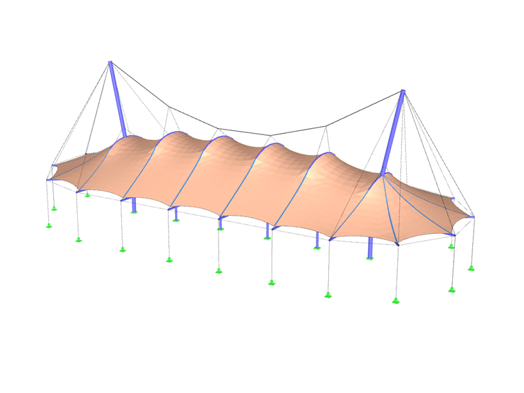
In RFEM, a global model was created for the form-finding process as well as for the membrane and supporting steel structure design. In order to comply with all required clearance profiles and avoid the formation of water pockets, a differentiated form-finding procedure was carried out, including applying prestress forces to individual components, others a defined target length, and some were excluded from the form-finding process altogether in order to adapt to the given boundary conditions according to their stiffness. The membrane fabric was modeled as an orthotropic surface.
Project Location
Selhurstpark Rd, Chichester PO18 0PSKeywords
Membrane structure Cable structure Roof structure PVC membrane Form-finding Pattern planning Water pocket formation Pylon
Write Comment...
Write Comment...
Contact Us
Do you have any further questions or need advice? Contact us via phone, email, chat or forum or find suggested solutions and useful tips on our FAQ page, available 24/7.

New
Evaluating and Documenting Steel Joints Analysis Results in RFEM 6
With the RFEM 6 add-on Steel Joints, you can analyze steel connections by using an FE model. This article demonstrates how to evaluate and document the steel joints analysis results.

New
- The design of the connection components is performed according to Eurocode EN 1993-1-8
- After activating the Add-on, the design situations for Steel Connections must be activated in the "Load cases and Combinations" dialog box
- For the design of the connection stability (Buckling), it is necessary to have the Add-on Structure Stability activated
- The calculation can be started via the table or via the icon in the top bar
-
How do I set a release for warping?
- How can I define a warping spring or a warping restraint?
- At which point on a cross-section are the supports and loads assumed for the calculation with warping torsion?
- The limit stress is activated, but my stress ratio is “non-designable” in the Stress-Strain Analysis add-on. What could be the reason?
- How can I deactivate the 7th degree of freedom for certain members or cross-sections only?
- How can I define a warping spring or a warping restraint?