


Structure
The engineering office D-Bois was responsible for the study of the new college courtyard.
The sawtooth roof sections of the courtyard are largely covered by translucent polycarbonate sheets, allowing natural light to enter.
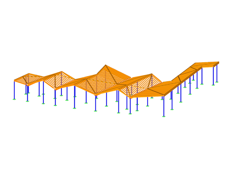
The self-supporting frame is made of a timber and metal multi-material. 41 tubular galvanized steel poles are made of circular hollow sections with a maximum height of 5 m (16.5 ft). The frame structure consists of ridge purlins and beams with built-up cross-sections (for gutters) made of glued-laminated timber GL24h. These elements rest on posts, the centers of which vary between 1 m (3.3 ft) and 6 m (19.8 ft). The frame is completed by load-bearing Chevron bracing and C24 softwood bracing.
Structural Design in RFEM 5
RFEM 5 was used to model and reduce the loads of this courtyard. The design checks of timber elements according to Eurocode 5 and steel elements according to Eurocode 3 were carried out with the RF-TIMBER Pro and RF-STEEL EC3 add-on modules.
A tubular column base model with stiffeners was required for stress analysis and design.
Since the structure is a Category III building located in Seismic Zone 3, a seismic analysis was carried out using the add-on modules RF‑DYNAM Pro – Natural Vibrations and RF‑DYNAM Pro – Equivalent Loads.
| Location | 15 rue de l'Elle 88510 Éloyes France |
| Investor | Vosges Departmental Council |
| Architect | FRANCOIS HENRION MALGRAS ARCHITECTES |
| Engineering Office | D-Bois |
.jpg.jpg?mw=720&hash=1d324a84ebd92b7cfab09d9251ff8e807b3a7c9a)
.jpg?mw=720&hash=e6f371b3c7d20432b945869c34e71bf3515178ef)
.jpg?mw=720&hash=113c57176deab5279183adb7e770a792117eac43)

.jpg.jpg?mw=240&hash=d05f5aad082307d14a2e542d008d906e0f8ed4e5)
.jpg?mw=240&hash=033615766038ddc7544cc61b4b40d730ea4b94e0)
.jpg?mw=240&hash=0355d118e8a9cf406ce2cf72e4fa4cf1ab5d852d)
