56 Results
View Results:
Sort by:

Lateral-Torsional Buckling (LTB) is a phenomenon that occurs when a beam or structural member is subjected to bending and the compression flange is not sufficiently supported laterally. This leads to a combination of lateral displacement and twisting. It is a critical consideration in the design of structural elements, especially in slender beams and girders.

The three types of moment frames (Ordinary, Intermediate, Special) are available in the Steel Design add-on of RFEM 6. The seismic design result according to AISC 341-22 is categorized into two sections: member requirements and connection requirements.

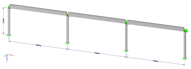
Moment frame design according to AISC 341-16 is now possible in the Steel Design add-on of RFEM 6. The seismic design result is categorized into two sections: member requirements and connection requirements. This article covers the required strength of the connection. An example comparison of the results between RFEM and the AISC Seismic Design Manual [2] is presented.

The three types of moment frames (Ordinary, Intermediate, Special) are available in the Steel Design add-on of RFEM 6. The seismic design result according to AISC 341-16 is categorized into two sections: member requirements and connection requirements.

The Steel Design add-on in RFEM 6 now offers the ability to perform seismic design according to AISC 341-16 and AISC 341-22. Five types of seismic force-resisting systems (SFRS) are currently available.

In RF‑/FOUNDATION Pro, the available reinforcing steel diameters can be adjusted by the user. The adjustment of the available rebar diameters works similarly to the same function in the RF‑/CONCRETE (Members) and RF‑/CONCRETE Columns add‑on modules.

The design of an Ordinary Concentrically Braced Frame (OCBF) and a Special Concentrically Braced Frame (SCBF) can be carried out in the Steel Design add-on of RFEM 6. The seismic design result according to AISC 341-16 and 341-22 is categorized into two sections: Member Requirements and Connection Requirements.

If you want to use a pure surface model, for example, when determining the internal forces and moments, but the structural component is still designed on the member model, you can take advantage of a result beam.

This article discusses the options available for determining the nominal flexural strength, Mnlb for the limit state of local buckling when designing according to the 2020 Aluminum Design Manual.

RF-CONCRETE Members for RFEM or CONCRETE for RSTAB propose an automatically created reinforcement to the user if the "Design the provided reinforcement" option is selected in Window 1.6 "Reinforcement".

In RF-/FOUNDATION Pro, the foundation design requires the definition of the corresponding loading (load cases, load combinations, or result combinations) for different design situations (STR, GEO, UPL, or EQU).

RF-PUNCH Pro performs punching shear design on concentrated load application locations (column connection, nodal support, and nodal load) as well as on wall ends and wall corners.

In RF‑/FOUNDATION Pro, you now have the option to design a foundation at one or several nodes of the model.
With RF-FOUNDATION Pro, it is possible to determine the settlements of single foundations and resulting spring stiffnesses of the nodal supports. These spring stiffnesses can be exported into the RFEM model and used for further analyses.

In RFEM 5 as well as RSTAB 8 in RF-/FOUNDATION Pro, you can save the foundation dimensions for all five foundation types as foundation templates in a user-defined database and use them later in other models.

In RF-/FOUNDATION Pro, the user can freely select the proportion of the relieving soil pressure by means of the factor kred.

In RFEM and RSTAB, different graphical representations of the foundation dimensions are available.

The effects due to snow load are described in the American standard ASCE/SEI 7-16 and in Eurocode 1, Parts 1 through 3. These standards are implemented in the new RFEM 6 program and the Snow Load Wizard, which serves to facilitate the application of snow loads. In addition to this, the most recent generation of the program allows the construction site to be specified on a digital map, thus allowing the snow load zone to be imported automatically. These data are, in turn, used by the Load Wizard to simulate the effects due to the snow load.

To perform deflection analysis in the right manner, it is important to “inform” the program about the exact support conditions of the element of interest. The definition of design supports in RFEM 6 will be shown for a reinforced concrete member set.

In RF-/FOUNDATION Pro, you can also consider the concrete cover for the foundation according to EN 1992-1-1.