152 Results
View Results:
Sort by:

Defining the appropriate effective length is crucial in obtaining the correct member design capacity. For X-bracing that is connected at the center, engineers often wonder if the full end-to-end length of the member shall be used, or whether using half of the length to where the members are connected is sufficient. This article outlines the recommendations given by the AISC and provides an example on how to specify the effective length of the X-braces in RFEM.

When it comes to wind loads on building type structures as per ASCE 7, numerous resources can be found to supplement design standards and aid engineers with this lateral load application. However, engineers may find it more difficult to find similar resources for wind loading on non-building type structures. This article will examine the steps to calculate and apply wind loads as per ASCE 7-16 on a circular reinforced concrete tank with a dome roof.

The wind load of rectangular rounded structural components is a complex matter. The equivalent forces from wind load depend on the strength of the circulating wind load and the component geometry.

In Germany, DIN EN 1991-1-4 with the National Annex DIN EN 1991-1-4/NA regulates the wind loads. The standard applies to civil engineering works up to an altitude of 300 m.

Wind blowing parallel to the surfaces of a structure can generate friction forces on these surfaces. This effect is important mainly for very large structures.

The design of a torsional loaded beam according to AISC Design Guide 9 will be shown, based on a verification example. The design will be performed with the RF‑STEEL AISC add-on module and the RF‑STEEL Warping Torsion module extension with 7 degrees of freedom.

Both the determination of natural vibrations and the response spectrum analysis are always performed on a linear system. If nonlinearities exist in the system, they are linearized and thus not taken into account. They are caused by, for example, tension members, nonlinear supports, or nonlinear hinges. This article shows how you can handle them in a dynamic analysis.

Torsional buckling analysis of transverse and longitudinal stiffeners with open cross-sections is described in DIN EN 1993-1-5, Chapter 9. There is a difference between the simplified method and the precise method, which takes into consideration the warping stiffness of the buckling panel. The simplified method applies Equation 9.3 of DIN EN 1993‑1‑5. If warping stiffness is to be taken into account, either Eq. 9.3 or Eq. 9.4 should be followed. Both design methods are implemented in PLATE-BUCKLING.

Wind direction plays a crucial role in shaping the outcomes of Computational Fluid Dynamics (CFD) simulations and the structural design of buildings and infrastructures. It is a determining factor in assessing how wind forces interact with structures, influencing the distribution of wind pressures, and consequently, the structural responses. Understanding the impact of wind direction is essential for developing designs that can withstand varying wind forces, ensuring the safety and durability of structures. Simplified, the wind direction helps in fine-tuning CFD simulations and guiding structural design principles for optimal performance and resilience against wind-induced effects.

Buckling analysis according to the effective width method or the reduced stress method is based on the determination of the system critical load, hereinafter called LBA (linear buckling analysis). This article explains the analytical calculation of the critical load factor as well as utilization of the finite element method (FEM).

For the stability design of members and sets of members with a uniform cross-section, you can use the equivalent member method according to EN 1993-1-1, 6.3.1 to 6.3.3. However, as soon as a tapered cross-section is available, this method can no longer be used, or only used to a limited extent. The RF-/STEEL EC3 add-on module can automatically recognize these cases and switch to the general method.

RF-PUNCH Pro performs punching shear design on concentrated load application locations (column connection, nodal support, and nodal load) as well as on wall ends and wall corners.

In RF-STEEL Surfaces, it is possible to display the stresses relevant for the design of welds, for example, according to EN 1993‑1‑8, Figure 4.5. When evaluating the stress components, the local xyz-axis system of the surfaces must be considered.

In SHAPE-THIN, the calculation of stiffened buckling panels can be performed according to Section 4.5 of EN 1993-1-5. For stiffened buckling panels, the effective surfaces due to local buckling of the single panels in the plate and in the stiffeners, as well as the effective surfaces from the entire panel buckling of the stiffened entire panel, have to be considered.

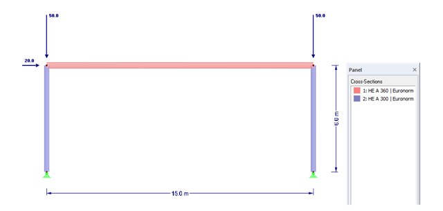
This technical article analyzes the effects of the connection stiffness on the determination of internal forces, as well as the design of connections using the example of a two-story, double-spanned steel frame.
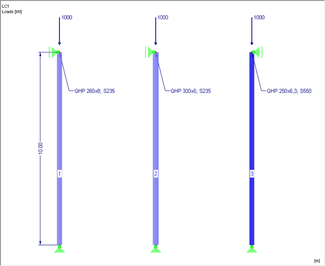
This article is about the stability analysis of a steel column with axial compression according to EN 1993‑1‑1, Clause 6.3.1. Additionally, a variation study is carried out aiming at steel optimization.

Diagonals of double angles are used for pipe bridge construction and for truss girders, among other things. They are usually subjected to tension, but it is necessary to transfer them in smaller compression forces with regard to the load application. In the case of slender diagonals in particular, you should also consider the bending due to self‑weight.

In this technical article, a hinged column with a centrally acting axial force and a line load acting on the strong axis will be designed by means of the RF-/STEEL EC3 add-on module according to EN 1993-1-1.

The RF‑/STEEL Warping Torsion module extension of the RF‑/STEEL EC3 add‑on module allows you to design members with asymmetric cross‑sections. The new option is fully integrated in the design module and can be activated for sets of members.

This technical article deals with the stability analysis of a roof purlin, which is connected without stiffeners by means of a bolt connection on the lower flange to have a minimum manufacturing effort.

- 001530
- Modeling | Loading
- RFEM 5
-
- RSTAB 8
- RX-TIMBER Glued-Laminated Beam 2
- RX-TIMBER Roof 2
- RX-TIMBER Continuous Beam 2
- RX-TIMBER Purlin 2
- RX-TIMBER Frame 2
- RX-TIMBER Column 2
- RX-TIMBER Brace 2
- Buildings
- Concrete Structures
- Steel Structures
- Timber Structures
- Process Manufacturing Plants
- Temporary Structures
- Structural Analysis & Design
- Eurocode 1
- Eurocode 0
In Germany, DIN EN 1991-1-3 with National Annex DIN EN 1991-1-3/NA regulates snow loads. The standard applies to civil engineering works at altitudes of up to 1,500 m above sea level.

In the existing standard, there were no regulations for the distribution of snow loads for elevated solar thermal and photovoltaic systems on roofs. Only distribution of the loads was advised. It was only with the National Annex DIN EN 1991-1-3/NA: 2019-04 that specific regulations were made for this.

The Steel Joist Institute (SJI) previously developed Virtual Joist tables to estimate the section properties for Open Web Steel Joists. These Virtual Joist sections are characterized as equivalent wide-flange beams which closely approximate the joist chord area, effective moment of inertia, and weight. Virtual Joists are also available in the RFEM and RSTAB cross-section database.

A previous article describes the design of double angles. It deals with analysis performed on a single member.
Critical load factors and the corresponding mode shapes of any structure can be determined efficiently in RFEM and RSTAB, using the RF-STABILITY or RSBUCK add-on module (linear eigenvalue solver or nonlinear analysis).
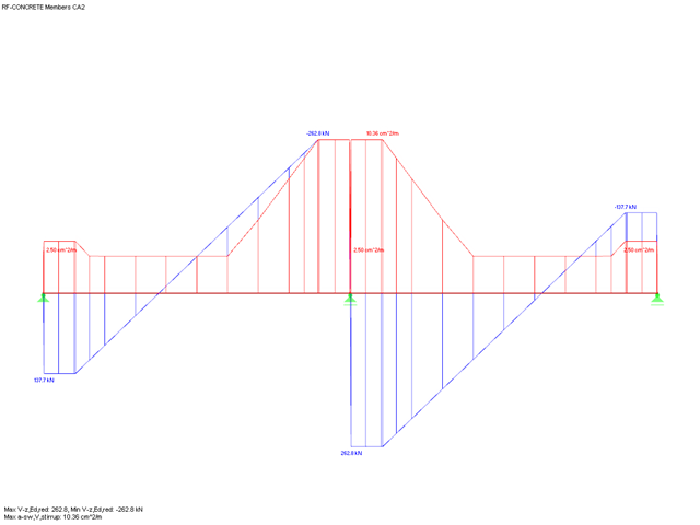
When performing shear force design in RF-CONCRETE Members and CONCRETE, you can reduce the acting shear force Vz according to EN 1992-1-1. The following article describes the reduction of the concentrated loads close to the support and the shear force design at the distance d from the support face for a uniform load.

Cross-section properties in RFEM and RSTAB include different types of shear areas. This technical article explains the calculation and meaning of various values.

In RF-/FOUNDATION Pro, you can also consider the concrete cover for the foundation according to EN 1992-1-1.

In RF-/FOUNDATION Pro, the foundation design requires the definition of the corresponding loading (load cases, load combinations, or result combinations) for different design situations (STR, GEO, UPL, or EQU).

DIN EN 1998-1 with the National Annex DIN EN 1998-1/NA specifies how to determine seismic loads. The standard applies to structural engineering in seismic areas.