154 Results
View Results:
Sort by:

The national parameters of EN 1992‑1‑1 for each country can be exported from RF‑/CONCRETE, RF‑/CONCRETE Columns, and RF‑/FOUNDATION Pro. To do this, there are interfaces with MS Excel, OpenOffice, and CSV. By exporting the national parameters, you can edit them in (for example) MS Excel, and display possible differences between the individual National Annexes clearly (see the image).

The three types of moment frames (Ordinary, Intermediate, Special) are available in the Steel Design add-on of RFEM 6. The seismic design result according to AISC 341-22 is categorized into two sections: member requirements and connection requirements.

Moment frame design according to AISC 341-16 is now possible in the Steel Design add-on of RFEM 6. The seismic design result is categorized into two sections: member requirements and connection requirements. This article covers the required strength of the connection. An example comparison of the results between RFEM and the AISC Seismic Design Manual [2] is presented.

The three types of moment frames (Ordinary, Intermediate, Special) are available in the Steel Design add-on of RFEM 6. The seismic design result according to AISC 341-16 is categorized into two sections: member requirements and connection requirements.

RF‑/FOUNDATION Pro introduced the geotechnical design of single foundations according to EN 1997‑1 in RFEM 5 and RSTAB 8. Depending on the National Annex preset in the add‑on module, you can determine the bearing resistance using Approach 2 or 3 in compliance with EN 1997‑1 up to Version x.04.0108.

When calculating foundations according to EC 7 or EC 2, different foundation types or sizes are usually used in one object. However, boundary conditions like the soil parameters, the materials for foundations, concrete covers, and the load combinations selected for design remain the same for all foundations, as a rule.

The Steel Design add-on in RFEM 6 now offers the ability to perform seismic design according to AISC 341-16 and AISC 341-22. Five types of seismic force-resisting systems (SFRS) are currently available.

In RF-/FOUNDATION Pro, a graphical display of the result details is available. To see them, go to Window 2.2 Governing Design Criteria after the calculation. In the interactive graphic of this window, individual design-relevant values can be displayed for each design performed.

Various optimizations are available with program version x.06.1103. The RF-/FOUNDATION Pro add-on module has also been subjected to further development.

The automatic surface reinforcement design process determines a surface reinforcement that covers the required amount of reinforcement.

RFEM 6 offers the Aluminum Design add-on for the design of aluminum members. This article shows how class 4 sections are designed according to Eurocode 9 in the program.

The determined values for the influence ordinates are displayed as decimal numbers with up to six decimal places by default. This is usually sufficient for the influence lines of internal forces.

The Steel Joist Institute (SJI) previously developed Virtual Joist tables to estimate the section properties for Open Web Steel Joists. These Virtual Joist sections are characterized as equivalent wide-flange beams which closely approximate the joist chord area, effective moment of inertia, and weight. Virtual Joists are also available in the RFEM and RSTAB cross-section database.

For foundation design, it is necessary to define the relevant loads for the respective design situations (STR, GEO, UPL, EQU).

Plate girder is an economical choice for long spans construction. I-section steel plate girder typically has a deep web to maximize its shear capacity and flange separation, yet thin web to minimize the self-weight. Due to its large height-to-thickness (h/tw) ratio, transverse stiffeners may be required to stiffen the slender web.

With RFEM version 5.06, member stiffnesses can be influenced by methods that are aligned with US steel construction standard ANSI/AISC 360-10. According to this standard, reduction factor τb must be considered for the determination of internal forces in all members of which the flexural resistance contributes to the model's stability. This coefficient depends on the axial force in the member: The larger the axial force, the larger τb is.

After running an analysis in RF-/STEEL AISC, the mode shapes for sets of members can be viewed graphically in a separate window. Select the relevant set of members in the result window and click the [Mode Shapes] button.

In RF‑/FOUNDATION Pro, the available reinforcing steel diameters can be adjusted by the user. The adjustment of the available rebar diameters works similarly to the same function in the RF‑/CONCRETE (Members) and RF‑/CONCRETE Columns add‑on modules.

The design of an Ordinary Concentrically Braced Frame (OCBF) and a Special Concentrically Braced Frame (SCBF) can be carried out in the Steel Design add-on of RFEM 6. The seismic design result according to AISC 341-16 and 341-22 is categorized into two sections: Member Requirements and Connection Requirements.
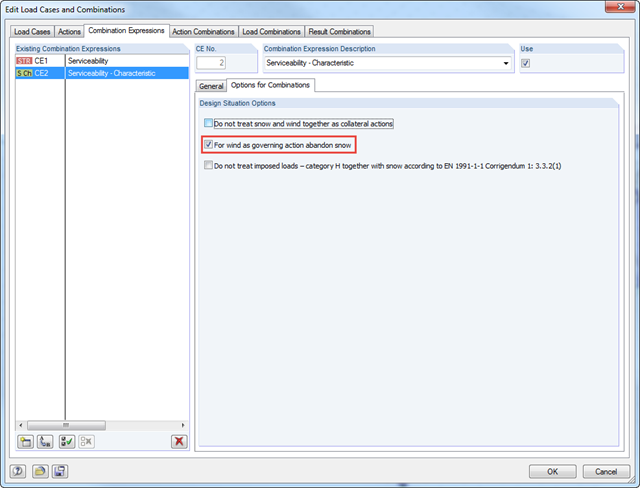
According to DIN EN 1990/NA:2010‑12 - NDP to A.1.2.1(1) Comment 2, it is possible to neglect the combination of snow as a collateral action in cases of wind/snow combination with wind as the leading action in wind zones III and IV.

Custom sections are often required in cold-formed steel design. In RFEM 6, the custom section can be created using one of the “Thin-Walled” sections available in the library. For other sections that do not meet any of the 14 available cold-formed shapes, the sections can be created and imported from the standalone program, RSECTION. For general information on AISI steel design in RFEM 6, refer to the Knowledge Base article provided at the end of the page.

The CSA S16:19 Stability Effects in Elastic Analysis method in Annex O.2 is an alternative option to the Simplified Stability Analysis Method in Clause 8.4.3. This article will describe the requirements of Annex O.2 and application in RFEM 6.

If you want to use a pure surface model, for example, when determining the internal forces and moments, but the structural component is still designed on the member model, you can take advantage of a result beam.

Foundations including dimensions can be saved as a template in a user-defined database.

In order to be able to carry out a pushover analysis, it is necessary to transform the determined capacity curve into a simplified form. The N2 method is described in Eurocode EN 1998. This article should help to explain what a bilinearization according to the N2 method involves.

The fatigue design according to EN 1992-1-1 must be performed for the structural components subjected to large stress ranges and/or many load changes. In this case, the design checks for the concrete and the reinforcement are performed separately. There are two alternative design methods available.

RF‑CONCRETE Surfaces for RFEM 5 allows you to use averaged internal forces for design of concrete surfaces.

In the case of using slow‑curing concrete (usually for thick components), you can reduce the calculated minimum reinforcement by a factor of 0.85 to apply the load due to restraint, according to EN 1992‑1‑1, Section 7.3.2. However, a precondition for reduction is that the characteristic value of the strength development r = fcm2 / fcm28 does not exceed 0.3. Other key requirements for the application of this reinforcement reduction are specified explicitly in the final planning documents.

In RF‑/TIMBER Pro, it is also possible to define the effective length for lateral-torsional buckling. The effective length for lateral-torsional buckling is then calculated according to EN 1995‑1‑1, Table 6.1. This option is useful especially for non-uniform load introduction.

RF-CONCRETE Members for RFEM or CONCRETE for RSTAB propose an automatically created reinforcement to the user if the "Design the provided reinforcement" option is selected in Window 1.6 "Reinforcement".