31 Results
View Results:
Sort by:
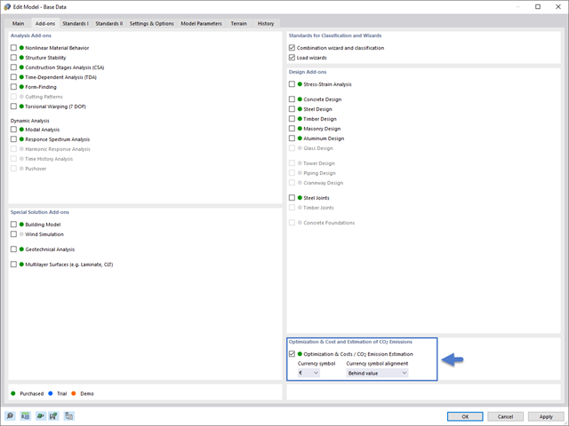
This article will show you how to optimize global parameters in RFEM 6 according to different aspects.

RFEM and RSTAB programs provide parameterized input as an advantageous product feature to create or adjust models by means of variables. This article will show you how to define global parameters and use them in formulas to determine numerical values.

The German Annex to EN 1992‑1‑1, the National Addition NCI to Article 9.2.1.2 (2), recommends to dispose the tension reinforcement in the flange plate of T‑beam cross‑sections on a maximum of one width corresponding to the half of a computed effective flange width beff,i according to Expression (5,7a).
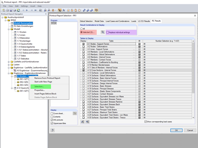
The content to be displayed in the loading and result tables can be managed in the global selection of the printout report (red).

The most common causes of unstable models are failing member nonlinearities such as tension members. As the simplest example, there is a frame with supports on the column footing and moment hinges on the column head. This unstable system is stabilized by a cross bracing of tension members. In the case of load combinations with horizontal loads, the system remains stable. However, if it is loaded vertically, both tension members fail and the system becomes unstable, which causes a calculation error. You can avoid such an error by selecting the exceptional handling of failing members under "Calculate" → "Calculation Parameters" → "Global Calculation Parameters".

For the stability design of members and sets of members with a uniform cross-section, you can use the equivalent member method according to EN 1993-1-1, 6.3.1 to 6.3.3. However, as soon as a tapered cross-section is available, this method can no longer be used, or only used to a limited extent. The RF-/STEEL EC3 add-on module can automatically recognize these cases and switch to the general method.
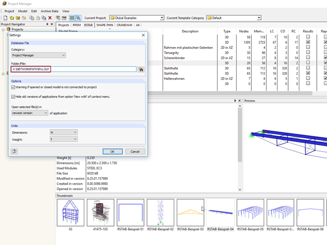
Due to rapid development in the IT sector, including structural design, the trend is towards a global model. Large projects are rarely carried out by a single engineer. Unified project management is the key to successful work in major projects.

Before creating a structural model, every user gives thought to the boundary parameters of the system and how best to represent the model. Special attention should be paid to the orientation of the global coordinate system. In engineering, the global Z‑axis is usually oriented downwards (in the direction of the dead load), while it tends to be upwards in architecture. These differences can often lead to complications during modeling; for example, when you replace global models or DXF layers.

If nonlinear effects - such as failing supports, foundations, member nonlinearities, or contact solids - are used in the model, you can deactivate them in the global calculation parameters.
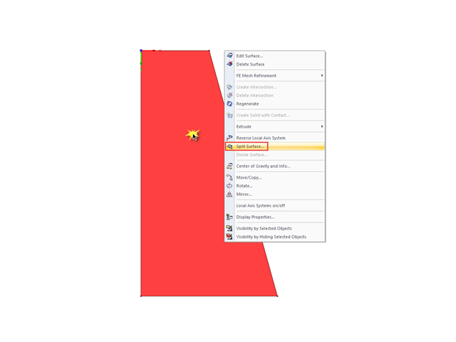
If you want to split a surface limited by four sides into several surfaces, the easiest way to do this is to use the "Split Surface" function.
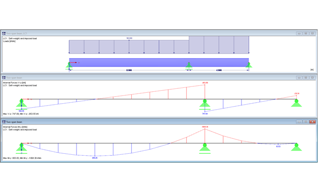
The following article describes designing a two-span beam subjected to bending by means of the RF-/STEEL EC3 add-on module according to EN 1993-1-1. The global stability failure will be excluded due to sufficient stabilizing measures.
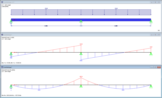
The cross-section class of a two-span beam will be designed in the following text. In addition, the necessary cross-section designs will be performed. The global stability failure will be excluded due to sufficient stabilizing measures.
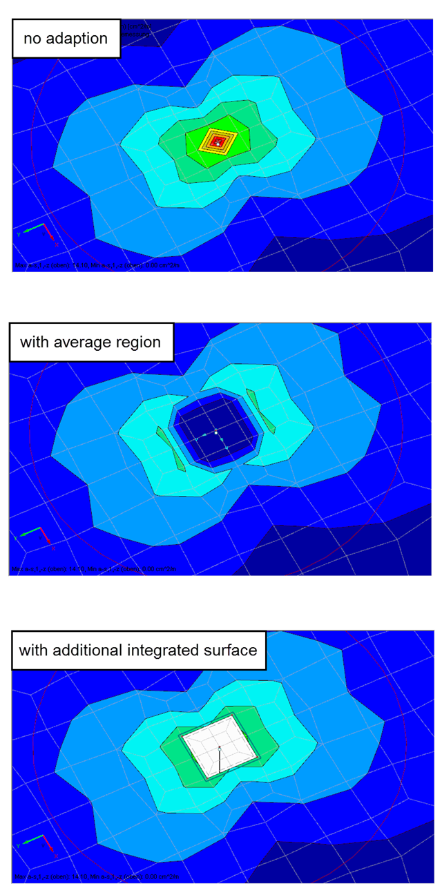
Singularities occur in a limited area due to the concentration of the stress-dependent result values. They are conditioned by the FEA methodology. In theory, the stiffness and/or the stress in an infinite size concentrate on an infinitesimally small area.
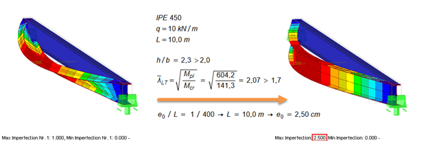
According to EN 1993‑1‑1 [1], it is necessary to use the equivalent geometric imperfections with values that reflect the possible effects of all types of imperfections. EN 1993‑1‑1, Section 5.3, specifies basic imperfections for the global analysis of frames as well as member imperfections.
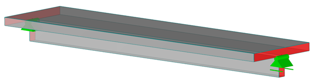
RFEM and the RF-CONCRETE add-on modules provide various options for the deformation analysis of a T-beam in the cracked state (state II). This technical article describes the calculation methods (C) and modeling options (M). Both the calculation methods and the modeling options are not limited to T-beams, but will only be explained using this system as an example.
According to EN 1993-1-1 [1], it is necessary to use the equivalent geometric imperfections with values that reflect the possible effects of all types of imperfections. EN 1993-1-1, Section 5.3, specifies basic imperfections for the global analysis of frames as well as member imperfections.
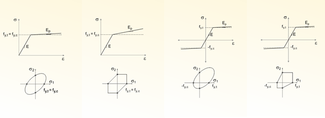
One of my earlier articles described the Isotropic Nonlinear Elastic material model. However, many materials do not have purely symmetrical nonlinear material behavior. In this regard, the yield laws according to von Mises, Drucker-Prager and Mohr-Coulomb mentioned in this previous article are also limited to the yield surface in the principal stress space.
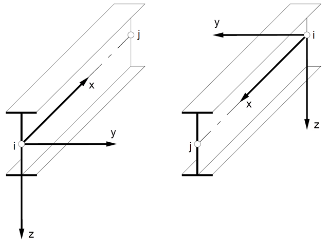
In spatial structures, the member position plays an important role in terms of determining internal forces. The orientation of member axes can be defined either by a global cross-section rotation angle, or by a specific member rotation angle. These two angles are added to determine the position of the main axes of a member in a 3D model.
![Residual Stresses, Zero Line Position, and Tearing Depth when Cooling Pane on both Sides [2]](/en/webimage/009621/2419687/01-en-png-png.png?mw=640&hash=5e657e3feb5c1bb6d21727468dd85d91e1c9f29f)
Generally, avoiding cracking in concrete structures is neither possible nor necessary. However, cracking must be limited in a way so that the proper use, appearance, and durability of the structure are not affected. Therefore, limiting the crack width does not mean preventing from the crack formation, but restricting the crack width to harmless values.
Pushover analysis is a nonlinear structural calculation for seismic analysis of structures. The load pattern is inferred from the dynamic calculation of equivalent loads. These loads are increased incrementally until global failure of the structure occurs. The nonlinear behaviour of a building is usually represented by using plastic hinges.

Nodal supports are usually defined with regard to the global axis system. However, it is sometimes necessary to rotate the nodal support. For example, for a floor slab with a pile foundation. For geological reasons, the piles do not rest in the ground vertically, but in an inclined position. Each end point of the piles has a nodal support that can only absorb forces along the pile foundation direction. Therefore, rotating the nodal support is required. Various options for this are described in previous posts.
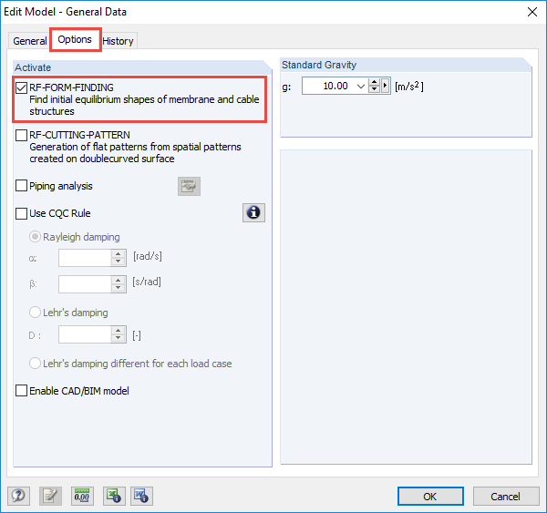
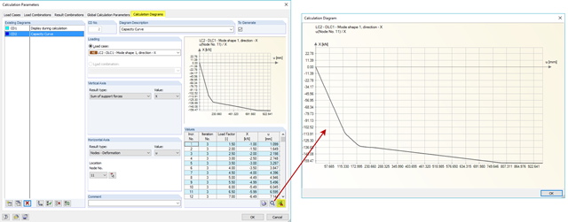
The RF-FORM-FINDING add-on module determines equilibrium shapes of membrane and cable elements in RFEM. In this calculation process, the program searches for such geometric position where the surface stress/prestress of membranes and cables is in equilibrium with natural and geometric boundary conditions. This process is called form-finding (hereinafter referred to as FF). The FF calculation can be activated in RFEM globally in the "General Data" of a model, "Options" tab. After selecting the corresponding option, a new load case or a calculation process called RF-FORM-FINDING is created in RFEM. An additional FF parameter is available for defining surface stress and prestress when entering cables and membranes. By activating the FF option, the program always starts the form-finding process before the pure structural calculation of internal forces, deformation, eigenvalues, etc., and generates a corresponding prestressed model for further analysis.
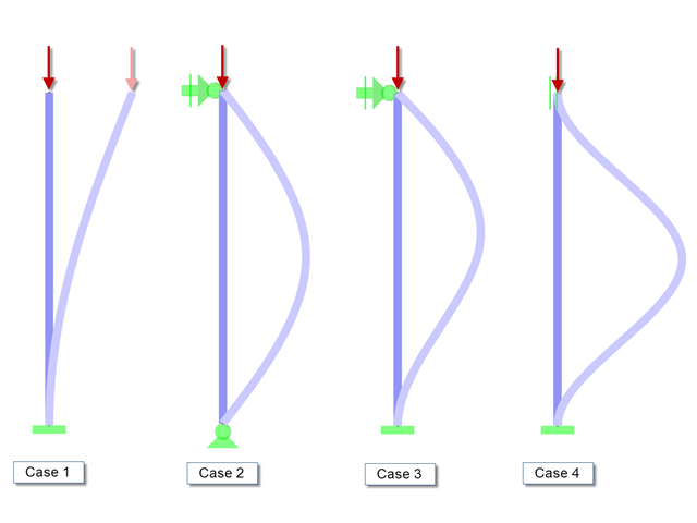
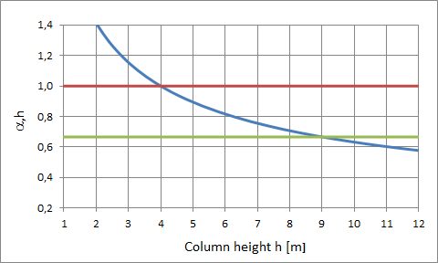
When performing the stability analysis of members according to the equivalent member method, considering internal forces according to the linear static analysis, it is very important to determine the governing equivalent member lengths.
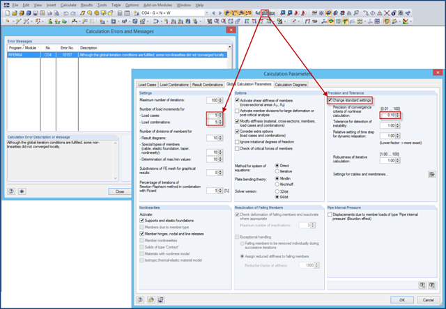
If nonlinearities are used in a model (for example, contact solids), an error message may appear at the end of the calculation due to the locally unfulfilled convergence criteria. The reason for this is that the convergence of the global iteration conditions governs in the calculation.
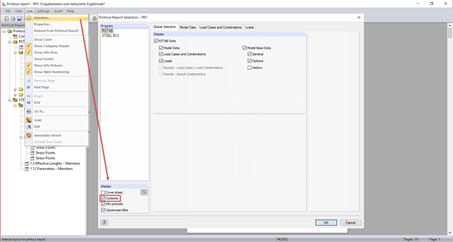
In the global selection of the printout report, you can select in the lower "Display" section whether you want to create a table of contents. The table of contents of the printout report usually requires too much space when displayed in one column.
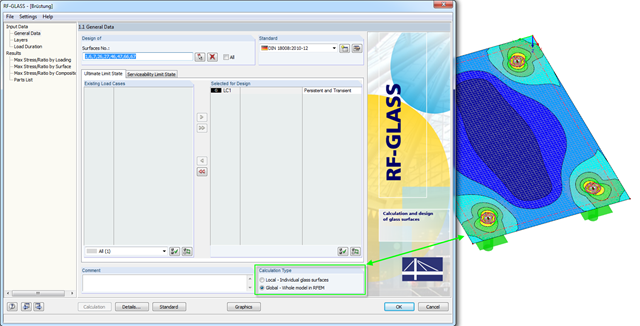
In RF-GLASS, two different calculation types are generally available in Window 1.1. There are the "Local" and the "Global" calculations.
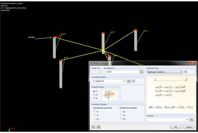
In the latest version of RFEM, nodal constraints were implemented. Therefore, you can now connect the nodes in an ideal way. The diaphragm type represents the option to couple nodes in a plane. This option is available not only for the global coordinate system, but also for user-defined coordinate systems.
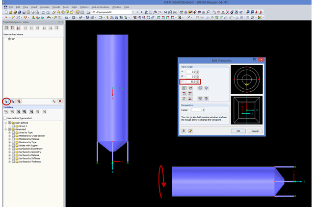
If you consider rotating the structure shown in the figure around the global Y‑axis, this might be not straightforward. In order to achieve better handling, the axis is always locked in the direction of your view. In the case of very high structures, it may be helpful to rotate the view about 90 degrees in the viewing direction.
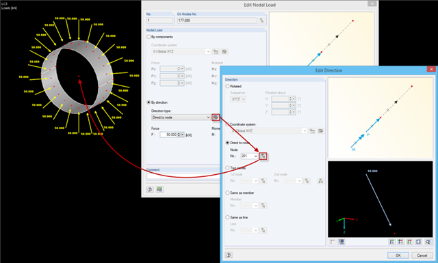
When defining nodal loads, you can rotate the load using several simple options: ~ Rotation by angle around the global coordinate axes in a specific order, ~ Alignment with a user-defined coordinate system, ~ Direction to a particular node, ~ Alignment by means of two nodes, ~ In the direction of a member/line.
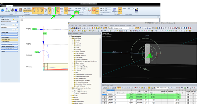
The equivalent loads determined in RF-TENDON due to prestress are transferred in RFEM as member loads or as line loads. A member load is used for member types with their own stiffness; a line load is used for member types without their own stiffness. In order to understand which values of the concentrated loads are to be transferred from RF‑TENDON to RFEM, you should use the following display settings: ~ Reference of the loads to the global coordinate system (GCS), ~ Load display: "Point"