18 Results
View Results:
Sort by:

Creating a validation example for Computational Fluid Dynamics (CFD) is a critical step in ensuring the accuracy and reliability of simulation results. This process involves comparing the outcomes of CFD simulations with experimental or analytical data from real-world scenarios. The objective is to establish that the CFD model can faithfully replicate the physical phenomena it is intended to simulate. This guide outlines the essential steps in developing a validation example for CFD simulation, from selecting a suitable physical scenario to analyzing and comparing the results. By meticulously following these steps, engineers and researchers can enhance the credibility of their CFD models, paving the way for their effective application in diverse fields such as aerodynamics, aerospace, and environmental studies.

Compliance with building codes, such as Eurocode, is essential to ensure the safety, structural integrity, and sustainability of buildings and structures. Computational Fluid Dynamics (CFD) plays a vital role in this process by simulating fluid behavior, optimizing designs, and helping architects and engineers meet Eurocode requirements related to wind load analysis, natural ventilation, fire safety, and energy efficiency. By integrating CFD into the design process, professionals can create safer, more efficient, and compliant buildings that meet the highest standards of construction and design in Europe.
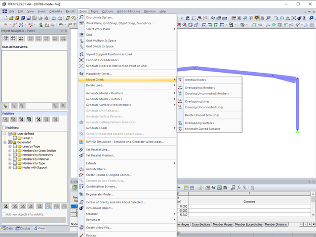
The model check allows you to search for discrepancies occurring during the modeling.

Before creating a structural model, every user gives thought to the boundary parameters of the system and how best to represent the model. Special attention should be paid to the orientation of the global coordinate system. In engineering, the global Z‑axis is usually oriented downwards (in the direction of the dead load), while it tends to be upwards in architecture. These differences can often lead to complications during modeling; for example, when you replace global models or DXF layers.
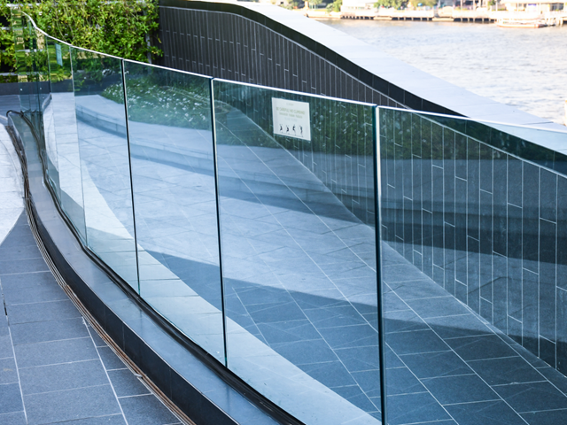
The architectural requirements for guardrails are still very high, and railings usually require a high degree of transparency. Glass railings, which do not require a visible support frame, offer a possible solution.

Closed circular cross-sections are ideal for welded truss structures. The architecture of such constructions is popular when designing transparent roofs. This article shows the special features of the connection design using hollow sections.
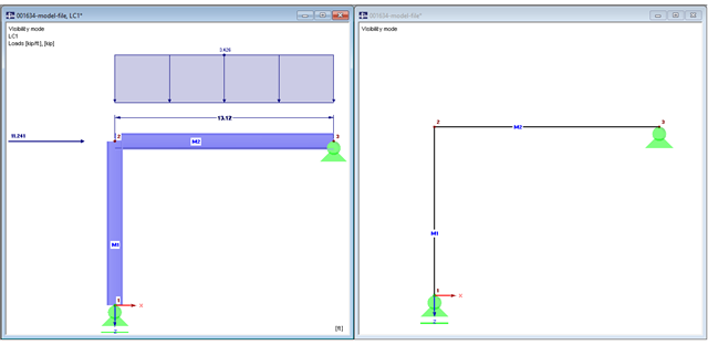
The beam is resting on the column, and the beam ends at the outer edge of the column. These requirements can be fulfilled easily in an architectural model with solids. In member analysis, simplified line models are used in which center lines meet in a common node. In this article, the influence of member eccentricities on the determination of internal forces is shown on three simple models.
.png?mw=640&hash=6e011ea537587ceb48d9e642d642150a151c551e)
The ASCE 7-16 standard requires both balanced and unbalanced snow load case scenarios for a structure's design consideration. While this may be more intuitive for flat or even gable/hip type roofs, the determination of snow loads is increasingly difficult for arch roofs due to complex geometry. However, with guidance from ASCE 7-16 on snow load calculations for curved roofs and RFEM's efficient load application tools, it is possible to consider both balanced and unbalanced snow loads for a reliable and safe structure design.
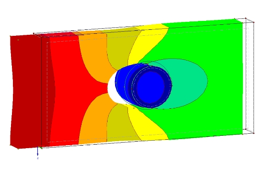
The definition of the non-linear contact problem plays an important role for more detailed investigations of shear/hole bearing connections or their immediate environment. This article uses a solid model to search for comparable and simplified surface models.
The proportion of glass used when planning a building is increasing. Open, light-flooded buildings represent the modern art of architecture. However, specialized engineers have to face new challenges during planning. One such example is ceiling-high glass facades loaded by a handrail. The influence of this loading, as well as the calculation of the deformation, are shown in this article.

Shell buckling is considered to be the most recent and least explored stability issue of structural engineering. This is due less to a lack of research activities than to the complexity of the theory. With the introduction and further development of the finite element method in structural engineering practice, some engineers no longer have to deal with the complicated theory of shell buckling. Evidence of the problems and errors to which this gives rise is very well summarized in [1].

Cable and tensile membrane structures are regarded as very slender and aesthetic building structures. The partly very complex double-curved shapes can be found using suitable form-finding algorithms. One possible solution is to search for the form via the equilibrium between the surface stress (provided prestress and an additional load such as self-weight, pressure, and so on) and the given boundary conditions.
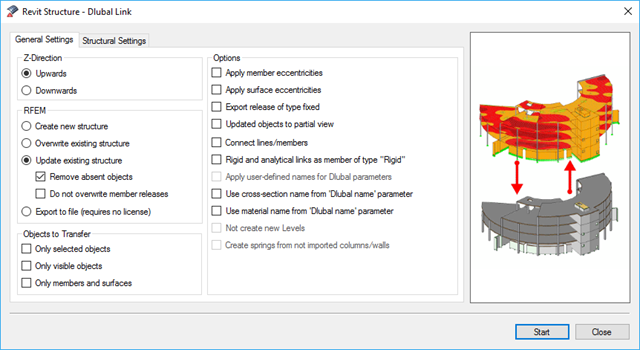
BIM is often used when it comes to data management in civil engineering. The individual disciplines of architecture, structural design, construction, and structural monitoring are coming closer together. Building Information Modeling makes this possible.. Dlubal Software provides a wide range of formats for data exchange. The following article explains the details of the interface with Autodesk Revit and, in particular, the export settings.
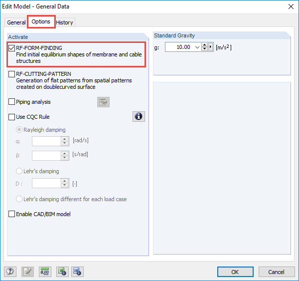
The RF-FORM-FINDING add-on module determines equilibrium shapes of membrane and cable elements in RFEM. In this calculation process, the program searches for such geometric position where the surface stress/prestress of membranes and cables is in equilibrium with natural and geometric boundary conditions. This process is called form-finding (hereinafter referred to as FF). The FF calculation can be activated in RFEM globally in the "General Data" of a model, "Options" tab. After selecting the corresponding option, a new load case or a calculation process called RF-FORM-FINDING is created in RFEM. An additional FF parameter is available for defining surface stress and prestress when entering cables and membranes. By activating the FF option, the program always starts the form-finding process before the pure structural calculation of internal forces, deformation, eigenvalues, etc., and generates a corresponding prestressed model for further analysis.
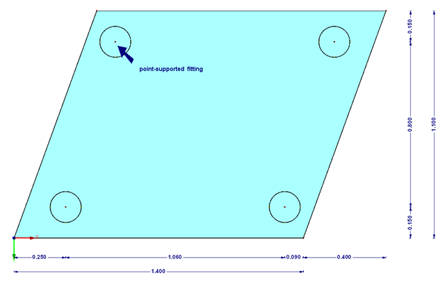
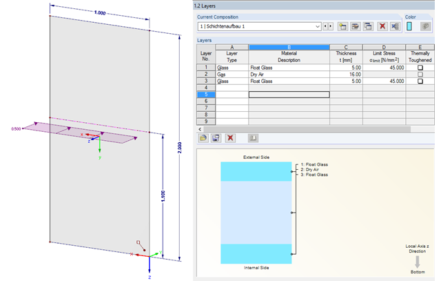
The transparency of the glass material should not be missing in any building. In addition to the typical application areas such as windows, this building material is increasingly being used for facades, canopies, or even as bracing of stairways. Of course, the planning architects often set a very high standard of transparency on fixation of the glass panes. This requires special glass fittings that couple the glass panes.
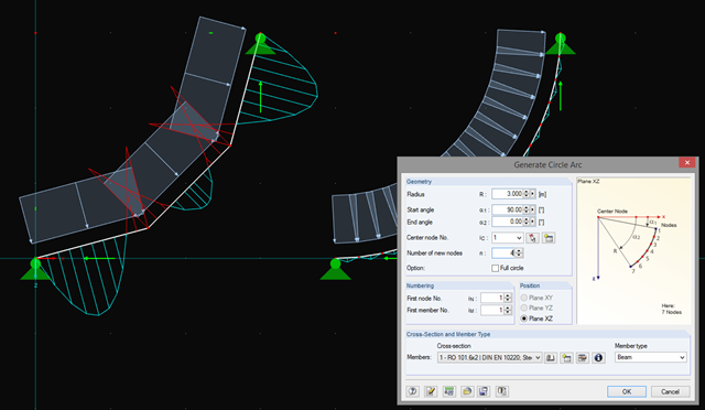
In addition to straight beams, it is sometimes necessary to calculate or design arched or circular beams in RSTAB. For this purpose, there is a special feature under "Tools" → "Generate Model – Members" → "Circle". You can easily use this tool to generate a full or pitch circle. The most important parameter here is the number of new nodes, which affects the accuracy of the results.
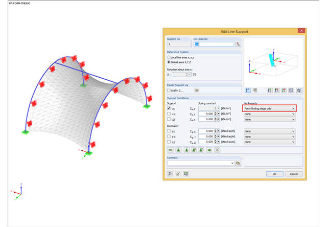
During the form-finding process, the slip modulus of a substructure is also taken into account when searching for the equilibrium state. You can also consider large deflections of supporting trusses or pure bending deformation of the edge beams when determining the membrane shape.
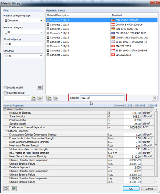
RFEM and RSTAB include an extensive materials library, which can be extended by user‑defined materials. Starting with version X.05, the materials library provides a convenient full‑text search. This way, you can find materials more quickly.