64 Results
View Results:
Sort by:
In the "Material Model - Isotropic Nonlinear Elastic" window, you can select the yield laws according to the von Mises, Tresca, Drucker-Prager, and Mohr-Coulomb yield rules. This makes it possible to describe the elasto-plastic material behavior. The yield function depends on the principal stresses or the invariants of a stress tensor. The criteria apply to 2D and 3D material models.

Both the determination of natural vibrations and the response spectrum analysis are always performed on a linear system. If nonlinearities exist in the system, they are linearized and thus not taken into account. They are caused by, for example, tension members, nonlinear supports, or nonlinear hinges. This article shows how you can handle them in a dynamic analysis.
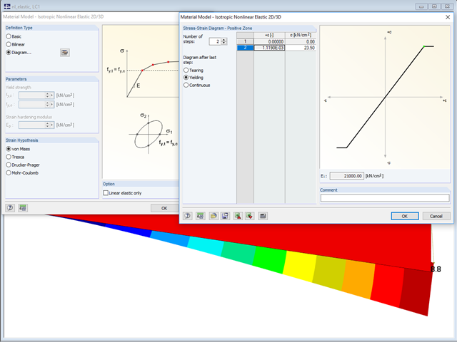
With the nonlinear elastic material model in RFEM 5, you can calculate and carry out a stress analysis of surfaces and solids with nonlinear material properties.

As you may already know, RFEM 6 offers you the possibility to consider material nonlinearities. This article explains how to determine internal forces in slabs modeled with nonlinear material.

The most common causes of unstable models are failing member nonlinearities such as tension members. As the simplest example, there is a frame with supports on the column footing and moment hinges on the column head. This unstable system is stabilized by a cross bracing of tension members. In the case of load combinations with horizontal loads, the system remains stable. However, if it is loaded vertically, both tension members fail and the system becomes unstable, which causes a calculation error. You can avoid such an error by selecting the exceptional handling of failing members under "Calculate" → "Calculation Parameters" → "Global Calculation Parameters".

Windbreak structures are special types of fabric structures which protect the environment from harmful chemical particles, abate wind erosion, and help to maintain valuable sources. RFEM and RWIND are used for wind-structure analysis as one-way fluid-structure interaction (FSI).
This article demonstrates how to structural design windbreak structures using RFEM and RWIND.

The Geotechnical Analysis add-on provides RFEM with additional specific soil material models that are able to suitably represent complex soil material behavior. This technical article is an introduction to show how the stress-dependent stiffness of soil material models can be determined.

The goal of using the RFEM 6 and Blender with the Bullet Constraints Builder add-on is to obtain a graphical representation of the collapse of a model based on real data of physical properties. RFEM 6 serves as the source of geometry and data for the simulation. This is another example of why it is important to maintain our programs as so-called BIM Open, in order to achieve collaboration across software domains.
Critical load factors and the corresponding mode shapes of any structure can be determined efficiently in RFEM and RSTAB, using the RF-STABILITY or RSBUCK add-on module (linear eigenvalue solver or nonlinear analysis).
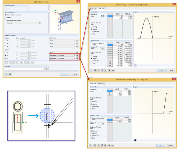
In RFEM, you can simulate a scaffolding tube joint (butt joint with a stub) by a nonlinear member release of the "Scaffolding" type. The joint considers moment resistance dependent on compression forces existing between two outer tubes, and the stub also has certain moment resistance based on its bending resistance.

In RFEM 5 and RSTAB 8, it is possible to assign nonlinearities to member hinges. In addition to the nonlinearities "Fixed if" and "Partial activity", you can select "Diagram". If you select the "Diagram" option, you have to specify the according settings for the activity of the member hinge. For the individual definition points, it is necessary to specify the abscissa and ordinate values (deformations or rotations and the according internal forces) that define the hinge.

If a rib is part of a nonlinear design or is rigidly connected to following walls, a surface should be used for the modeling instead of a member. So that the rib can still be designed as a member, a result member with the correct eccentricity is required, which transforms the surface internal forces into member internal forces.
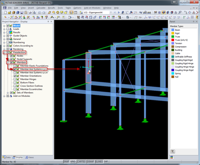
The local coordinate system of a member is particularly important when defining member end releases and member nonlinearities. The definitions follow the orientation of the axes. You can temporarily adjust the visibility of these member axes by means of preselection.

Shell buckling is considered to be the most recent and least explored stability issue of structural engineering. This is due less to a lack of research activities than to the complexity of the theory. With the introduction and further development of the finite element method in structural engineering practice, some engineers no longer have to deal with the complicated theory of shell buckling. Evidence of the problems and errors to which this gives rise is very well summarized in [1].

Plastic hinges are imperative for the Pushover Analysis (POA) as a nonlinear static method for the seismic analysis of structures. In RFEM 6, plastic hinges can be defined as member hinges. This article will show you how to define plastic hinges with bilinear properties.

The elastic deformations of a structural component due to a load are based on Hooke's law, which describes a linear stress-strain relation. They are reversible: After the relief, the component returns to its original shape. However, plastic deformations lead to irreversible deformations. The plastic strains are usually considerably larger than the elastic deformations. For plastic stresses of ductile materials such as steel, yielding effects occur where the increase in deformation is accompanied by hardening. They lead to permanent deformations - and in extreme cases to the destruction of the structural component.

Designing rigid end plate connections is difficult for four-row connection geometries and multi-axis bending stresses, because there are no official design methods.
Orthotropic material laws are used wherever materials are arranged according to their loading. Examples include fiber-reinforced plastics, trapezoidal sheets, reinforced concrete, and timber.
Numerous nonlinearities can occur in a structural system. The RF-DYNAM Pro - Nonlinear Time History add-on module was developed in order to model them realistically in a dynamic analysis. To explain how the add-on module works, the procedure is described below with an example.
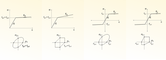
One of my earlier articles described the Isotropic Nonlinear Elastic material model. However, many materials do not have purely symmetrical nonlinear material behavior. In this regard, the yield laws according to von Mises, Drucker-Prager and Mohr-Coulomb mentioned in this previous article are also limited to the yield surface in the principal stress space.

The Nonlinear Material Behavior add-on enables the consideration of material nonlinearities in RFEM 6. This article provides an overview of the available nonlinear material models, which are available after activating the add-on in the model’s Base Data.

Describing the procedure for the serviceability limit state design of a floor slab made of steel fiber reinforced concrete. This article shows how to perform the corresponding design for the SLS by means of the iteratively determined FEA results.

Steel-fiber-reinforced concrete is mainly used nowadays for industrial floors or hall floors, foundation plates with low loads, basement walls, and basement floors. Since the publication in 2010 of the first guideline about steel-fiber-reinforced concrete by the German Committee for Reinforced Concrete (DAfStb), a structural engineer can use standards for the design of the steel fiber-reinforced concrete composite material, which makes the use of fiber-reinforced concrete increasingly popular in construction. This article describes the nonlinear calculation of a foundation plate made of steel fiber-reinforced concrete in the ultimate limit state with the FEA software RFEM.
When designing reinforced concrete components according to EN 1992‑1‑1 [1], nonlinear methods of determining internal forces for the ultimate and serviceability limit states are possible. In this case, the internal forces and deformations are determined with respect to their nonlinear behaviour. The analysis of stresses and strains in cracked state usually provides the deflections, which clearly exceed the linearly determined values.

Nodal releases are special objects in RFEM 6 that allow structural decoupling of objects connected to a node. The release is controlled by the release type conditions, which may also have nonlinear properties. This article will show the definition of nodal releases in a practical example.
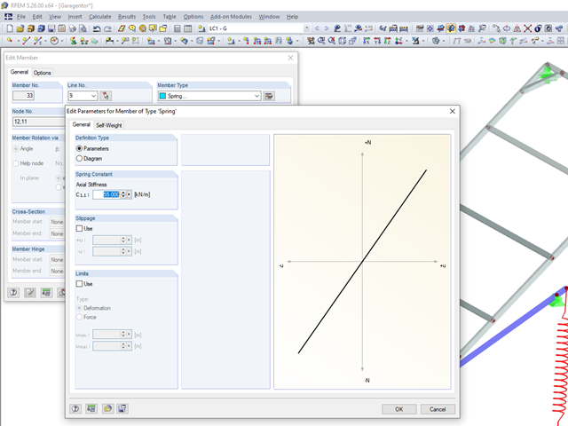
The RFEM5 and RSTAB8 programs offer a "Spring" option when defining a member under the member types.

You can model and analyze masonry structures in RFEM 6 with the Masonry Design add-on that employs the finite element method for the design. Complex masonry structures can be modeled, and static and dynamic analysis can be performed, given that a nonlinear material model is implemented in the program to display the load-bearing behavior of masonry and the different failure mechanisms. You can enter and model masonry structures directly in RFEM 6 and combine the masonry material model with all common RFEM add-ons. In other words, you can design entire building models in connection with masonry.
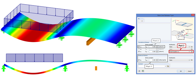
In order to increase the stiffness of a ceiling structure in case of renovation, visible downstand beams are used that are not connected to the ceiling structure. Nonlinear line releases can be used to transfer only the compression forces. If there are tensile forces between the ceiling and the downstand beam, as shown in the figure, the downstand beam does not transfer the stiffness in the overall structure.

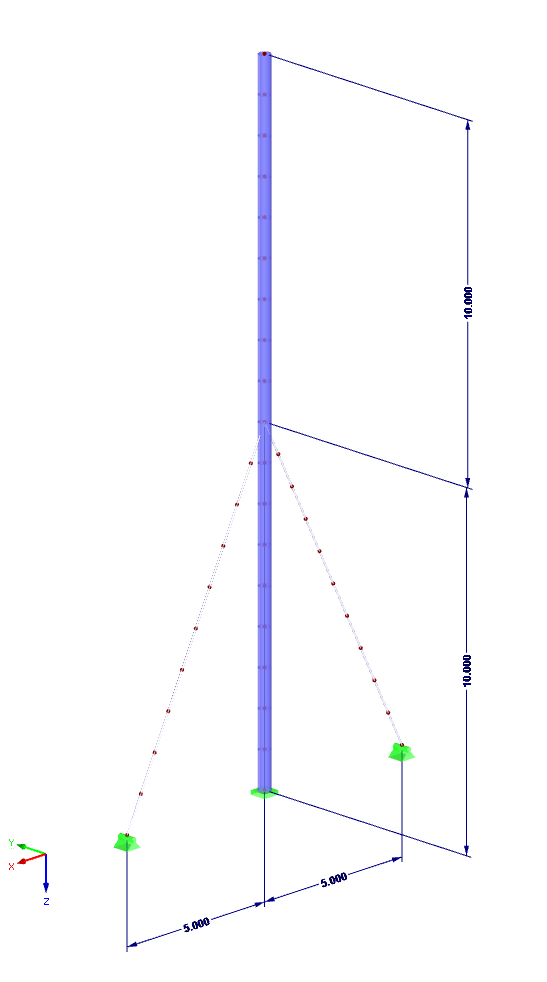
RFEM 5 allows you to use many different member nonlinearities for designing a model. In the following text, we look at an example of the use of the "slippage" member nonlinearity. The example is a simplified model of a concrete manhole with a square plan view.
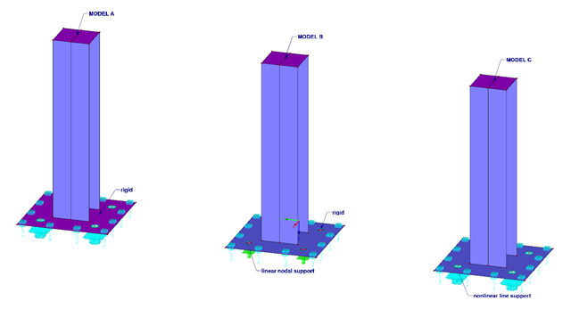
When designing column bases, high-performance anchors are often used for an anchorage. This article describes different models for a column footing and the evaluation thereof.