


Introduction
Soil shows a highly nonlinear material behavior. One of its significant properties is the stress dependence of the soil stiffness. The nonlinear elastic soil material model is appropriate for representing this stress-dependent stiffness.
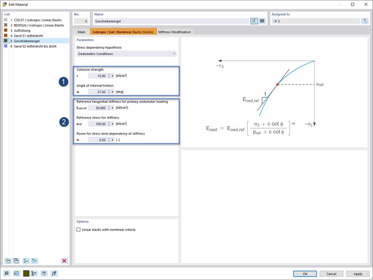
Once the "Soil" material type is set in the program and the nonlinear elastic "Isotropic | Soil | Nonlinear Elastic (Solids)” material model is selected, a specific input tab is available (Image 1).
Stress Dependence of Stiffness
The tab above (Image 1) provides a schematic representation of the stress-strain relation of soil in the dialog graphic.
The stress dependence used is expressed for the oedometric modulus with the following equation, according to [1]. It corresponds to the approach used in the hardening soil model.
The shear strengths (φ and c, see 1 in Image 1) can be taken directly from the geotechnical report of the respective project. Moreover, the following parameters (see 2 in Image 1) are required.
- Eoed,ref – reference value of oedometric tangent modulus
- pref – reference stress
- m – power for stress dependency
The stress dependence is controlled by the exponent m, which can be measured in both the oedometer test and the triaxial test. Typical values for sand are m = 0.5 and for clay, m = 1.0.
The reference value of the model's initial loading stiffness Eoed,ref can be derived from the constrained moduli of the geotechnical report by means of pref and m.
Determination of Parameters Eoed,ref, pref & m
This section will now show how to determine the parameters for the material model using an example.
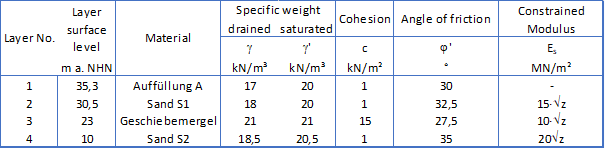
Geotechnical investigation for our example shows the following soil layers.
The calculation is carried out using the following steps:
- 1. Determination of available stresses in initial state
Based on the layers' soil properties and the layer heights, the effective overburden pressure σv‘ can be determined for the respective depth.
- 2. Stiffness of soil according to geotechnical report
The soil stiffness profile along the depth is known from the geotechnical report.
- 3. Stiffness calculated by formula of material model
The parameters of the material model are set in such a way that the stiffness profile resulting from the material model shows a satisfactory agreement with that of the expert assessment.
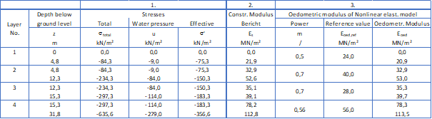
The stresses and stiffnesses shown in the table in Image 3 are the result for the present example.
Result
Image 4 below shows the distribution of the oedometric stiffness over depth in the initial stress state, as derived from the formula of the material model and used in the FE analysis. The stiffness profile from the geotechnical report is shown for comparison.
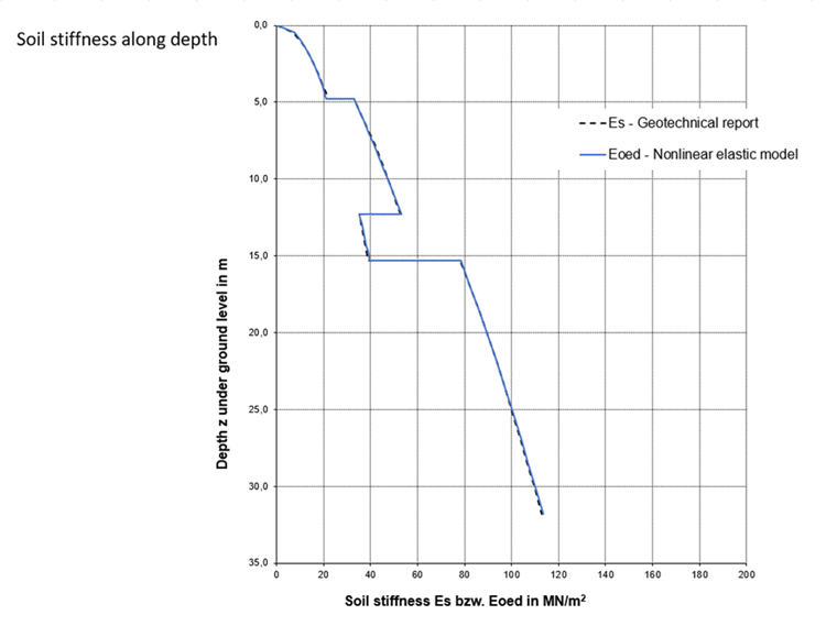
It becomes clear that the stiffness values Eoed applied represent the stiffness profile of the geotechnical report appropriately.
