336 Results
View Results:
Sort by:

In this article, the calculation of a timber panel wall with the beam panel thickness type is compared with a manual calculation.

Using the Timber Design add-on, timber column design is possible according to the 2018 NDS standard ASD method. Accurately calculating timber member compressive capacity and adjustment factors is important for safety considerations and design. The following article will verify the maximum critical buckling strength calculated by the Timber Design add-on using step-by-step analytical equations as per the NDS 2018 standard including the compressive adjustment factors, adjusted compressive design value, and final design ratio.

The three types of moment frames (Ordinary, Intermediate, Special) are available in the Steel Design add-on of RFEM 6. The seismic design result according to AISC 341-22 is categorized into two sections: member requirements and connection requirements.

The National Building Code of Canada (NBC) 2020 Article 4.1.8.7 provides a clear procedure for earthquake methods of analysis. The more advanced method, the Dynamic Analysis Procedure in Article 4.1.8.12, should be used for all structure types except those that meet the criteria set forth in 4.1.8.7. The more simplistic method, the Equivalent Static Force Procedure (ESFP) in Article 4.1.8.11, can be used for all other structures.

RWIND 2 and RFEM 6 can now be used to calculate wind loads from experimentally measured wind pressures on surfaces. Basically, two interpolation methods are available to distribute pressures measured in isolated points across the surfaces. The desired pressure distribution can be achieved using the appropriate method and parameter settings.

This article explains how the calculation in the initial stiffness analysis in Steel Joints works.

To evaluate whether it is also necessary to consider the second-order analysis in a dynamic calculation, the sensitivity coefficient of interstory drift θ is provided in EN 1998‑1, Sections 2.2.2 and 4.4.2.2. It can be calculated and analyzed using RFEM 6 and RSTAB 9.

For the ultimate limit state design, EN 1998‑1, Sections 2.2.2 and 4.4.2.2 require a calculation considering the second‑order theory (P‑Δ effect). This effect may be neglected only if the interstory drift sensitivity coefficient θ is less than 0.1.

The three types of moment frames (Ordinary, Intermediate, Special) are available in the Steel Design add-on of RFEM 6. The seismic design result according to AISC 341-16 is categorized into two sections: member requirements and connection requirements.

Moment frame design according to AISC 341-16 is now possible in the Steel Design add-on of RFEM 6. The seismic design result is categorized into two sections: member requirements and connection requirements. This article covers the required strength of the connection. An example comparison of the results between RFEM and the AISC Seismic Design Manual [2] is presented.

The design of an Ordinary Concentrically Braced Frame (OCBF) and a Special Concentrically Braced Frame (SCBF) can be carried out in the Steel Design add-on of RFEM 6. The seismic design result according to AISC 341-16 and 341-22 is categorized into two sections: Member Requirements and Connection Requirements.

Plate girder is an economical choice for long spans construction. I-section steel plate girder typically has a deep web to maximize its shear capacity and flange separation, yet thin web to minimize the self-weight. Due to its large height-to-thickness (h/tw) ratio, transverse stiffeners may be required to stiffen the slender web.

Using an example of a steel fiber-reinforced concrete slab, this article describes how the use of different integration methods and of a different number of integration points affects the calculation result.

When it comes to wind loads on building type structures as per ASCE 7, numerous resources can be found to supplement design standards and aid engineers with this lateral load application. However, engineers may find it more difficult to find similar resources for wind loading on non-building type structures. This article will examine the steps to calculate and apply wind loads as per ASCE 7-22 on a circular reinforced concrete tank with a dome roof.

Everything is online. The same is true for the Dlubal licenses for RFEM 6, RSTAB 9, and RSECTION. This article contains information about using and managing online licenses, reserving licenses, checking the license validity, and moving authorizations between the licenses.
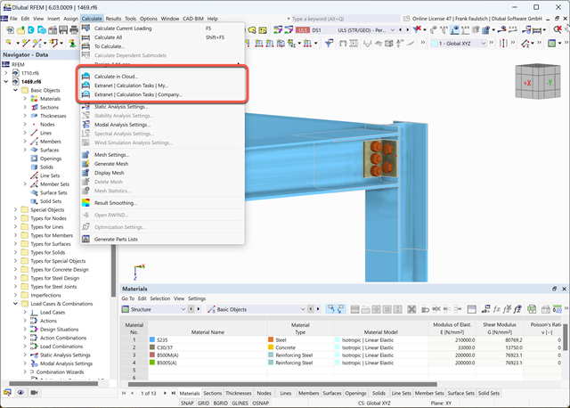
This article explains how the cloud calculation works.
![Spans Based on Figure 5.2 from [1]](/en/webimage/039540/3493372/01_Abmessungen_EN.png?mw=640&hash=a3c436931baff3514db261b2d11bfa39abae9170)
In order to correctly design a downstand beam or a T-beam in RFEM 6 using the Concrete Design add-on, it is essential to determine the flange widths for the rib members. This article describes the input options for a two-span beam and the calculation of the flange dimensions according to EN 1992-1-1.

CFD calculations are in general very complex. An accurate calculation of wind flow around complicated structures is very demanding on time and computational costs. In many civil engineering applications, high accuracy is not needed and our CFD program RWIND 2 enables in such cases to simplify the model of a structure and reduce the costs significantly. In this article, some questions about the simplification are answered.

In this article, a heavy cargo box is calculated according to the guidelines of the German Bundesverband Holzpackmittel (HPE). The load cases for Handling by Crane and Sea Transport are calculated.

Compliance with building codes, such as Eurocode, is essential to ensure the safety, structural integrity, and sustainability of buildings and structures. Computational Fluid Dynamics (CFD) plays a vital role in this process by simulating fluid behavior, optimizing designs, and helping architects and engineers meet Eurocode requirements related to wind load analysis, natural ventilation, fire safety, and energy efficiency. By integrating CFD into the design process, professionals can create safer, more efficient, and compliant buildings that meet the highest standards of construction and design in Europe.

This article shows how to create cross-sections using DXF files.

When calculating regular structures, data input is often not complicated but time-consuming. Input automation can save valuable time. The task described in the present article is to consider the stories of a house as single construction stages. Data is entered using a C# program so that the user does not have to enter the elements of the individual floors manually.

In many frame and truss structures, it is no longer sufficient to use a simple member. You often have to consider cross-section weakenings or openings in solid beams. In such cases, you can use the "Surface Model" member type. It can be integrated into the model like any other member and offers all the options of a surface model. The present technical article shows the application of such a member in an existing structural system and describes the integration of member openings.

To be able to evaluate the influence of local stability phenomena of slender structural components, RFEM 6 and RSTAB 9 provide you with the option of performing a linear critical load analysis on the cross-section level. The following article explains the basics of the calculation and the result interpretation.

When a concrete slab is set upon the top flange, its effect is like a lateral support (composite construction), preventing problems of torsional buckling stability. If there is a negative distribution of the bending moment, the bottom flange is subjected to compression and the top flange is under tension. If the lateral support given by the stiffness of the web is insufficient, the angle between the bottom flange and the web intersection line is variable in this case so that there is a possibility of distortional buckling for the bottom flange.

Large-scale models are models which contain multiple dimensional scales and thus are demanding on computational power. This article will show you how to simplify and optimize the calculation of such models with respect to the desired results.

Custom sections are often required in cold-formed steel design. In RFEM 6, the custom section can be created using one of the “Thin-Walled” sections available in the library. For other sections that do not meet any of the 14 available cold-formed shapes, the sections can be created and imported from the standalone program, RSECTION. For general information on AISI steel design in RFEM 6, refer to the Knowledge Base article provided at the end of the page.

RFEM 6 offers the Aluminum Design add-on for the design of aluminum members. This article shows how class 4 sections are designed according to Eurocode 9 in the program.

This article will show you the design of cold-formed steel cross-sections according to EN 1993-1-3, Section 6.1.6 in RFEM 6. Since the topic is still under development, the currently available options will be presented.

The design of cold-formed steel members according to the AISI S100-16 is now available in RFEM 6. Design can be accessed by selecting “AISC 360” as the standard in the Steel Design add-on. “AISI S100” is then automatically selected for the cold-formed design (Image 01).