78 Results
View results:
Sort by:

The data exchange between RFEM 6 and Allplan can be done using various file formats. This article describes the data exchange of a determined surface reinforcement using the ASF interface. This allows you to display the RFEM reinforcement values as level curves or colored reinforcement images in Allplan.

Creating a validation example for Computational Fluid Dynamics (CFD) is a critical step in ensuring the accuracy and reliability of simulation results. This process involves comparing the outcomes of CFD simulations with experimental or analytical data from real-world scenarios. The objective is to establish that the CFD model can faithfully replicate the physical phenomena it is intended to simulate. This guide outlines the essential steps in developing a validation example for CFD simulation, from selecting a suitable physical scenario to analyzing and comparing the results. By meticulously following these steps, engineers and researchers can enhance the credibility of their CFD models, paving the way for their effective application in diverse fields such as aerodynamics, aerospace, and environmental studies.

When calculating regular structures, data input is often not complicated but time-consuming. Input automation can save valuable time. The task described in the present article is to consider the stories of a house as single construction stages. Data is entered using a C# program so that the user does not have to enter the elements of the individual floors manually.

The goal of using the RFEM 6 and Blender with the Bullet Constraints Builder add-on is to obtain a graphical representation of the collapse of a model based on real data of physical properties. RFEM 6 serves as the source of geometry and data for the simulation. This is another example of why it is important to maintain our programs as so-called BIM Open, in order to achieve collaboration across software domains.

The Nonlinear Material Behavior add-on enables the consideration of material nonlinearities in RFEM 6. This article provides an overview of the available nonlinear material models, which are available after activating the add-on in the model’s Base Data.
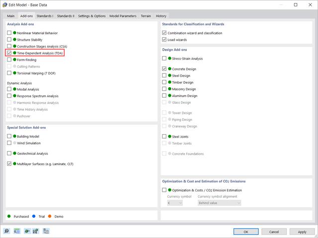
This article shows how the “Time-Dependent Analysis” add-on is integrated in RFEM 6 and RSTAB 9. It describes how to define input data such as the time-dependent characteristics of the material, how to determine the type of analysis and how to specify loading times.

The Steel Joist Institute (SJI) previously developed Virtual Joist tables to estimate the section properties for Open Web Steel Joists. These Virtual Joist sections are characterized as equivalent wide-flange beams which closely approximate the joist chord area, effective moment of inertia, and weight. Virtual Joists are also available in the RFEM and RSTAB cross-section database.

In RFEM 6 it is possible to define multilayer surface structures with the help of the “Multilayer Surfaces” add-on. Hence, if you have activated the add-on in the model’s Base Data, it is possible to define layer structures of any material model. You can also combine material models of, for example, isotropic and orthotropic materials.
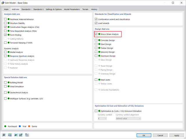
This article shows how to manage the input data for member and surface design configurations within the Stress-Strain Analysis add-on.

Given that realistic determination of the soil conditions significantly influences the quality of the structural analysis of buildings, the Geotechnical Analysis add-on is offered in RFEM 6 to determine the soil body to be analyzed.
The way to provide data obtained from field tests in the add-on and use the properties from soil samples to determine the soil massifs of interest was discussed in Knowledge Base article “Creation of the Soil Body from Soil Samples in RFEM 6”. This article, on the other hand, will discuss the procedure to calculate settlements and soil pressures for a reinforced concrete building.

The quality of the structural analysis of buildings is significantly improved when the soil conditions are considered as realistically as possible. In RFEM 6, you can realistically determine the soil body to be analyzed with the help of the Geotechnical Analysis add-on. This add-on can be activated in the model’s Base Data as shown in Image 01.
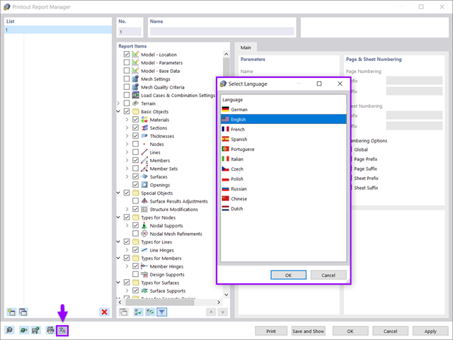
All data in RFEM 6 can be documented in a multilingual printout report. The design of the printout report is modern and has been highly optimized with respect to the previous (RFEM 5) generation of the program. Some of its most significant features are discussed in this article.

The effects due to snow load are described in the American standard ASCE/SEI 7-16 and in Eurocode 1, Parts 1 through 3. These standards are implemented in the new RFEM 6 program and the Snow Load Wizard, which serves to facilitate the application of snow loads. In addition to this, the most recent generation of the program allows the construction site to be specified on a digital map, thus allowing the snow load zone to be imported automatically. These data are, in turn, used by the Load Wizard to simulate the effects due to the snow load.

RFEM 6 includes the Form-Finding add-on to determine the equilibrium shapes of surface models subjected to tension and members subjected to axial forces. Activate this add-on in the model's Base Data and use it to find the geometric position in which the prestress of lightweight structures is in equilibrium with the existing boundary conditions.

Seismic Analysis in RFEM 6 is possible using the modal analysis and the response spectrum analysis add-ons. As a matter of fact, the general concept of the earthquake analysis in RFEM 6 is based on the creation of a load case for the modal analysis and the response spectrum analysis, respectively. The standard groups for these analyses are set in the Standards II tab of the model’s Base Data.
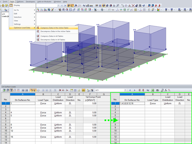
To ensure the well‑arranged structure of data in tables, the load data are organized automatically in RFEM and RSTAB.

Foundations including dimensions can be saved as a template in a user-defined database.

In RFEM 5 as well as RSTAB 8 in RF-/FOUNDATION Pro, you can save the foundation dimensions for all five foundation types as foundation templates in a user-defined database and use them later in other models.
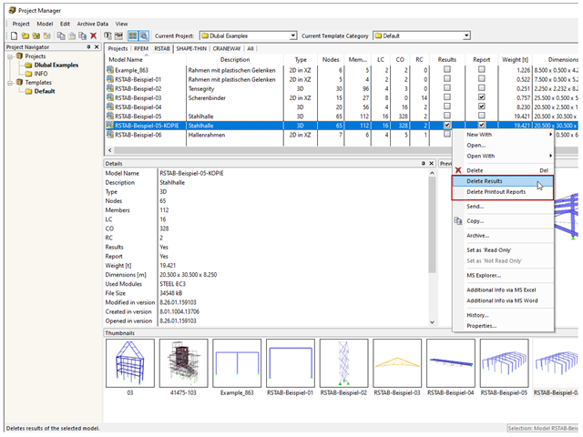
In rare cases, it may happen that an RFEM or RSTAB file cannot be opened. These files contain mostly results and report data.

RFEM and RSTAB save the input data, the FE mesh, the results, the printout reports, and the 3D gITF model preview, including all visual objects, in one file.
The network-capable Project Manager controls the projects of all Dlubal Software applications in one central location.

In the age of BIM, data exchange between the various disciplines of structural engineering is becoming increasingly important. Since each software has its own specifications with regard to the description of cross-sections and materials, RFEM and RSTAB offer a conversion table (mapping file).
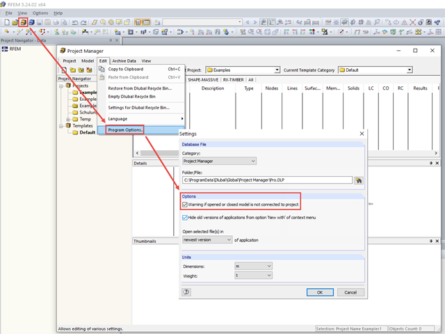
Warning Regarding Connection to Project
---
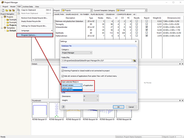
When opening a model immediately after opening the program, there is a message window asking if you want to create a new project for the model in the Project Manager.

The SHAPE‑THIN and SHAPE‑MASSIVE cross-section programs are suitable for determining the cross-section properties of common thin-walled or thick-walled sections. These cross-section properties are also available for further analyses in RSTAB and RFEM.
In the Formula Editor environment, you can specify any parameters (lengths, force values, and so on) to control load and geometry data in the modeling.
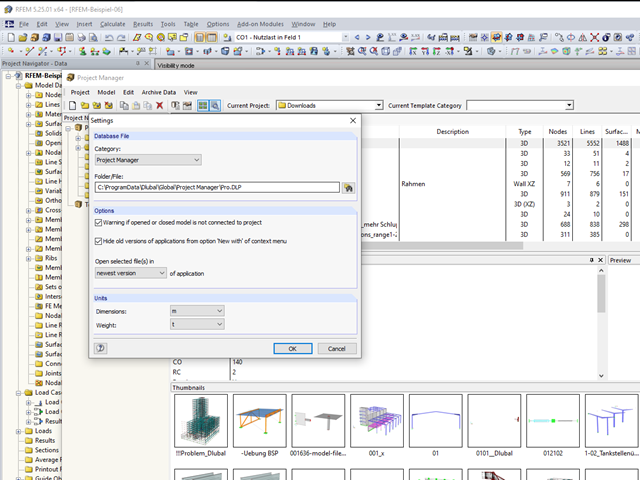
In RFEM and RSTAB, you can work with the Project Manager. It allows you to create an entire project structure and to connect it with the folders on the local hard disk.

In RF‑/STEEL EC3, you can assign the same input data to several members or sets of members at the same time. The simultaneous assignment of the input data is possible for intermediate supports, effective lengths, nodal supports, member end hinges, and shear panel and rotational restraint.
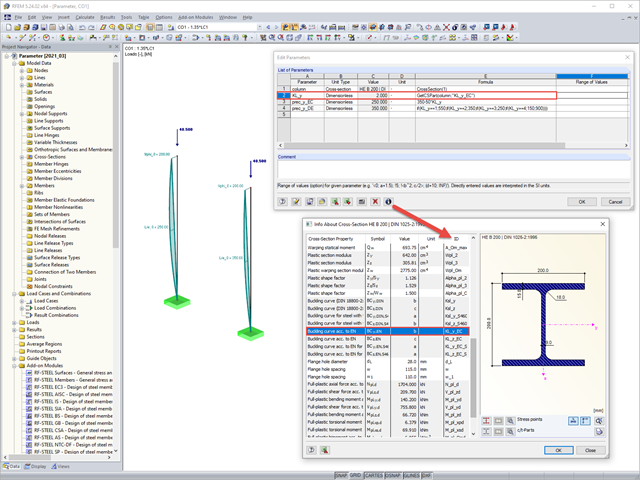
Parametric input allows you to enter the model data and load data in a specific way so they are dependent on certain variables (parameters). You can enter the parameters directly or calculate them from other parameters and constants, and furthermore, it is possible to access the cross-section values. This can be useful, for example, when calculating precambers, depending on the standard.
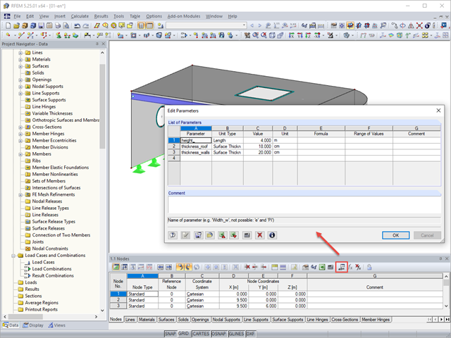
Parameterized entries provide the engineer with an efficiency-increasing tool. This allows entering structural and loading data so that they depend on certain variables. These variables (for example, length, width, live load, and so on) are called parameters.
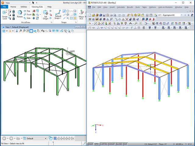
The ISM file (ISM = Integrated Structural Modeling) in RFEM and RSTAB provides an interesting option for exchanging data. If you export a model to this data format, you can view and analyze it with the free ISM viewer from Bentley.