Input
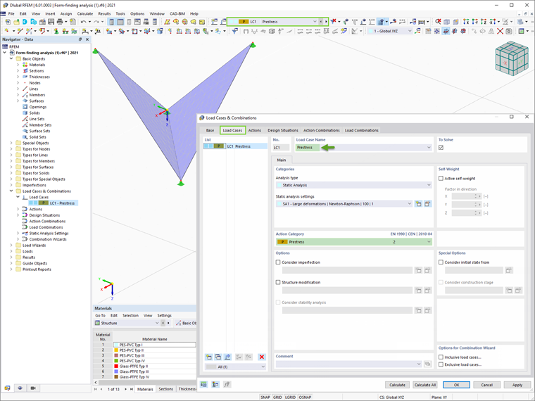
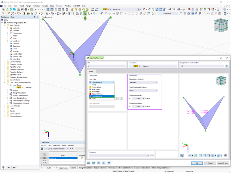
Once the structures are modeled in RFEM, the form-finding process can be initiated. In RFEM 6, this is done by assigning a load of the form-finding type to elements such as membranes and cables. The load should be defined in an exclusive load case with the load case category "Prestress", as shown in Image 1.
The input data for the surface load of the form-finding type applied to membranes includes the calculation method (standard or projection), the form-finding definition (force or stress), and the magnitude of the associated load (Image 2).
As a matter of fact, the standard method describes a vector that can move freely in space until it reaches the target position, whereas the projection method describes a vector that can move partially in space and is fixed to its XY coordinates. In general, the standard method should be preferred. The projection method is appropriate for models which are spanned around a central axis (conical shapes).
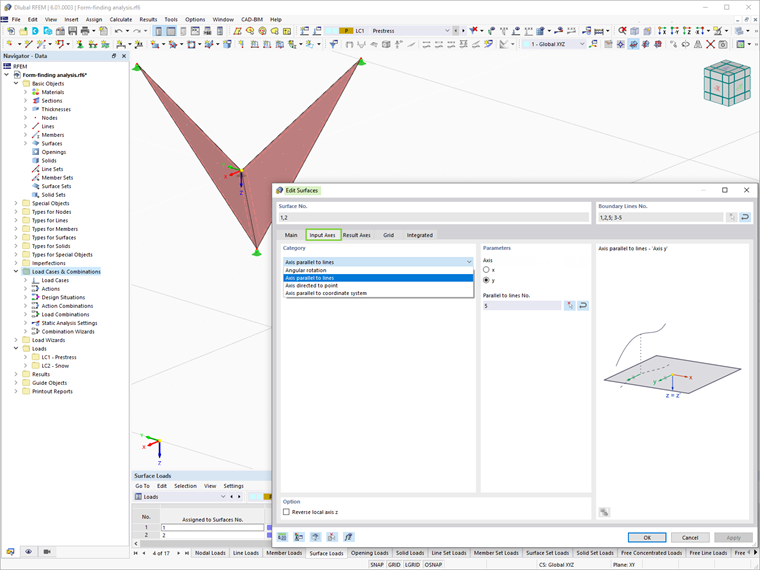
It is important to mention that to apply an orthotropic surface prestress, the Specific Axis option in the Main tab of the surface window should be checked, and the input parameters in Image 3 must be adjusted accordingly.
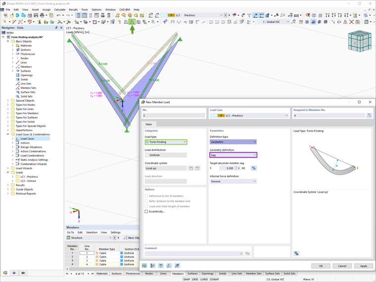
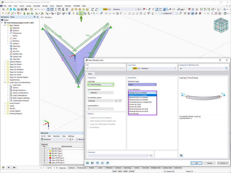
The member load of the form-finding type, on the other hand, can be geometric or introduced as a force. The former can be defined in terms of length, unstressed length, and sag (including maximum and low-point vertical sag). This is illustrated in Image 4. The latter can be defined as a force in member, tension at the ends, horizontal tension component, or force density (Image 5).
Analysis Settings
The analysis settings can be defined as shown in Image 6. In this way, the user can specify in how many iterations the form-finding calculation should apply the prestress to the elements with the previously defined value. When this limit is exceeded, the program stops repeatedly, applying the prestress with the start value during the form-finding calculation. In fact, increasing the allowable iterations can lead to better convergence.
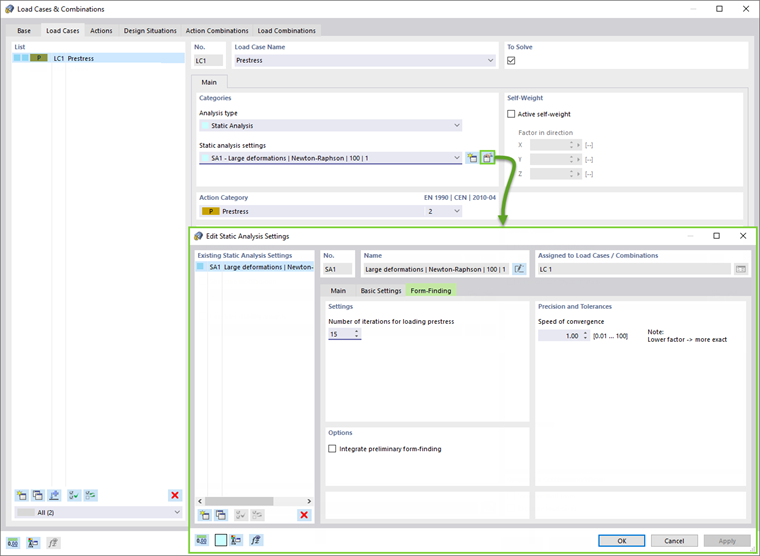
Next, the Speed of Convergence that controls the calculation stability can be adjusted. The form-finding calculation applies the absolute stiffness to the membrane surfaces, but the user can increase the stiffness by defining a value lower than 1. This results in slower convergence, but higher calculation stability.
The option to integrate the preliminary form-finding is also available in the settings. The preliminary form-finding displaces the FE surface elements by using the simple linear force-density method. Thus, the path between the initial position and the target position is usually reduced for the actual iterative form-finding process. That being the case, a certain amount of computing time is saved, and the global form-finding process is faster.
Results
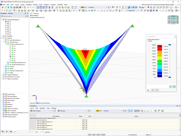
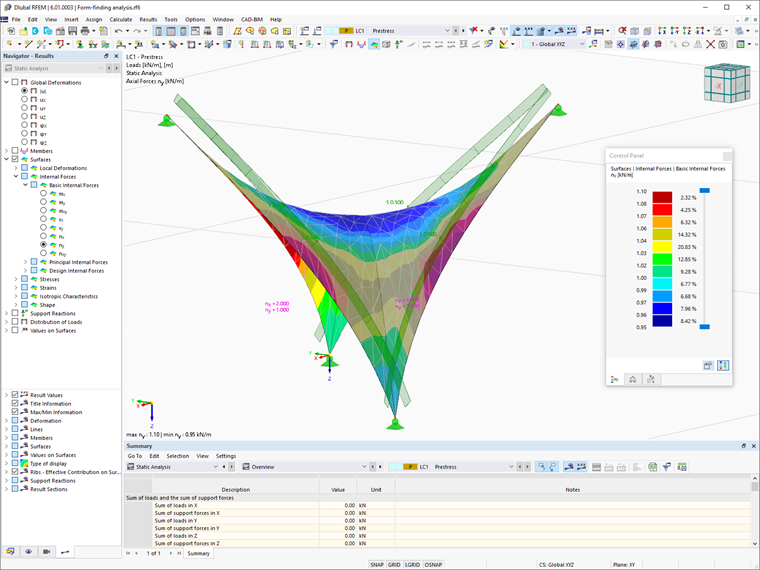
Once the load case has been calculated, deformations as well as member and surface results can be graphically displayed via the Results tab of the navigator. The former describes the deformation between the initial input and the determined equilibrium shape, whereas the latter includes the force or stress conditions for the equilibrium shape, considering the defined form-finding parameters. Examples of these results are provided in Images 7 and 8, respectively.
Subsequent Load Application
At this point, the available results represent a new model configuration. For further calculation and structural analysis of the overall model, the program transfers the form-found geometry including the element-wise strains into a universally applicable initial state for use in the load cases and load combinations.
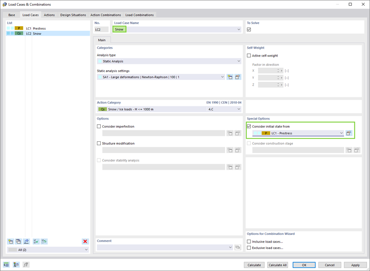
Thus, if a certain load should be applied afterwards, the initial state from the form-finding load case must be considered. In other words, the deformation in terms of subsequent load cases applies to the previously determined equilibrium shape.
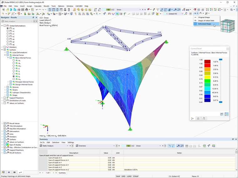
The option to consider the initial state from the form-finding load case can be activated as shown in Image 9. An example of such a load application is provided in Image 10, where snow is applied with respect to the equilibrium shape of the lightweight structure.