22 Wyniki
Wyświetl wyniki:
Sortuj według:

Niniejszy artykuł dotyczy długotrwałego ugięcia konstrukcji betonowych zgodnie z ACI 318 i CSA A23.3.

W tym artykule wyjaśniono różne metody dostępne w rozszerzeniu Analiza modalna, służące do określania liczby postaci własnych.

W tym artykule pokażemy, jak zdefiniować żebra podłużne na blasze pręta za pomocą komponentu „Żebro” w rozszerzeniu Połączenia stalowe.

Z tego artykułu dowiesz się, jak zamodelować proste połączenie z blachą czołową w programie RFEM 6.

Ocena przemieszczenia kondygnacji w budynku jest kluczowa dla zapewnienia zadowalających parametrów konstrukcyjnych poprzez ograniczenie przemieszczenia kondygnacji. Nadmierne znoszenie może powodować niestateczność systemu i powodować uszkodzenia elementów niekonstrukcyjnych, takich jak ściany działowe. W tym artykule opisano procedurę wyznaczania przemieszczeń międzykondygnacyjnych zgodnie z ASCE 7-22 i rozszerzeniem Model budynku w programie RFEM 6.

Zrozumienie sztywności połączeń stalowych ma kluczowe znaczenie w projektowaniu konstrukcji. Często połączenia są traktowane jako połączenia całkowicie sztywne lub przegubowe, co może prowadzić do nieekonomicznych lub nawet ryzykownych warunków projektowych. Dowiedz się, w jaki sposób program RFEM firmy Dlubal i rozszerzenie Połączenia stalowe pomagają weryfikować sztywność połączeń i nośność na zginanie, zapewniając bezpieczniejsze i bardziej ekonomiczne warunki projektowe.

W artykule przedstawiono podstawowe pojęcia z zakresu dynamiki konstrukcji i ich roli w projektowaniu konstrukcji sejsmicznych. Duży nacisk kładzie się na wyjaśnienie aspektów technicznych w zrozumiały sposób, aby tematyka była zrozumiała dla czytelników bez dużej wiedzy technicznej.

W tym artykule wyjaśniono, jak działają obliczenia podczas wstępnej analizy sztywności w programie Połączenia stalowe.

Aby ocenić, czy w obliczeniach dynamicznych konieczne jest również uwzględnienie analizy drugiego rzędu, w normie EN 1998‑1, sekcje 2.2.2 i 4.4.2.2 zawarto współczynnik wrażliwości międzykondygnacyjnego znoszenia θ. Można ją obliczyć i przeanalizować za pomocą programów RFEM 6 i RSTAB 9.
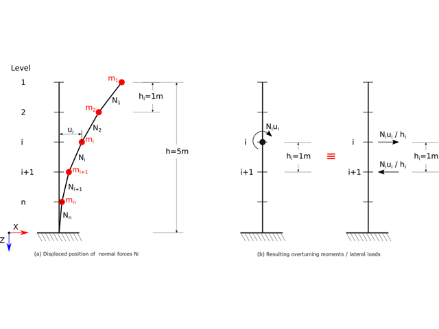
Zgodnie z normami EN 1998-1 sekcje 2.2.2 i 4.4.2.2 do obliczeń stanu granicznego nośności należy przeprowadzić obliczenia z uwzględnieniem teorii drugiego rzędu (efekt P-Δ). Efekt ten nie musi być uwzględniany tylko w przypadku, gdy współczynnik wrażliwości międzykondygnacyjnej jest mniejszy niż 0,1.

W tym artykule przedstawiono model połączenia zakładkowego płatwi ZL na dachu jednospadowym, obliczony w rozszerzeniu Połączenia stalowe i porównany z tabelą nośności podaną przez producenta.

Zarówno analiza drgań własnych, jak i analiza spektrum odpowiedzi przeprowadzane są na układzie liniowym. Jeżeli w modelu występują nieliniowości, podlega on linearyzacji, dzięki czemu elementy nieliniowe nie są brane pod uwagę w dalszej analizie. Mogą to być na przykład pręty rozciągane, podpory nieliniowe lub przeguby nieliniowe. W tym artykule pokazano, w jaki sposób można nimi zarządzać w analizie dynamicznej.

W tym artykule opisujemy, w jaki sposób można używać rozszerzenia Skręcanie skrępowane (7 stopni swobody) i Stateczność konstrukcji w celu uwzględnienia deplanacji przekroju jako dodatkowego stopnia swobody podczas analizy stateczności.

Analiza dynamiczna w RFEM 6 i RSTAB 9 jest podzielona na kilka rozszerzeń. Rozszerzenie Analiza modalna jest niezbędne dla wszystkich innych rozszerzeń do analizy dynamicznej, ponieważ przeprowadza analizę drgań własnych dla modeli prętów, powierzchni i brył.

Analiza modalna jest punktem wyjścia do analizy dynamicznej układów konstrukcyjnych. Można ją wykorzystać do określenia wartości drgań własnych, takich jak częstotliwości drgań własnych, kształty drgań własnych, masy modalne i efektywne współczynniki masy modalnej. Wynik ten może zostać wykorzystany do obliczeń drgań oraz do dalszych analiz dynamicznych (na przykład obciążenia widmem odpowiedzi).
Konstrukcje murowe można modelować i analizować w programie RFEM 6 za pomocą rozszerzenia Projektowanie konstrukcji murowych, który wykorzystuje do obliczeń metodę elementów skończonych. Zakładając, że w programie zaimplementowano nieliniowy model materiałowy, można modelować złożone konstrukcje murowe oraz przeprowadzać analizę statyczną i dynamiczną, aby przedstawić nośność konstrukcji murowej oraz różne mechanizmy uszkodzenia. Istnieje możliwość wprowadzania i modelowania konstrukcji murowych bezpośrednio w programie RFEM 6 oraz łączenia modelu materiałowego muru ze wszystkimi popularnymi rozszerzeniami dla programu RFEM. Umożliwia to projektowanie całych modeli budynków w połączeniu z murem.

Zaletą modułu dodatkowego RFEM 6 Steel Joints jest możliwość analizy połączeń stalowych przy użyciu modelu MES, dla którego modelowanie przebiega w pełni automatycznie w tle. Elementy składowe złącza stalowego, które kontrolują modelowanie, można wprowadzić, definiując je ręcznie lub korzystając z dostępnych szablonów w bibliotece. Ta ostatnia metoda została opisana w poprzednim artykule z Bazy wiedzy zatytułowanym „Definiowanie komponentów połączenia stalowego przy użyciu biblioteki”. Definiowanie parametrów do wymiarowania połączeń stalowych jest tematem artykułu w bazie wiedzy „Projektowanie połączeń stalowych w RFEM 6”.

W programie RFEM 6 połączenia stalowe definiuje się jako układ elementów. W nowym rozszerzeniu Połączenia stalowe dostępne są podstawowe komponenty do uniwersalnego zastosowania (blachy, spoiny, płaszczyzny pomocnicze). Metody definiowania połączeń opisano w dwóch poprzednich artykułach w Bazie informacji: „Nowe podejście do wymiarowania połączeń stalowych w programie RFEM 6” oraz „Definiowanie elementów połączenia stalowego przy użyciu biblioteki” .

Dzięki rozszerzeniu Połączenia stalowe dla RFEM 6 można tworzyć i analizować połączenia stalowe przy użyciu wydzielonego modelu ES. Modelowanie połączeń można kontrolować poprzez proste i wygodne wprowadzanie elementów. Elementy stalowego połączenia można definiować ręcznie lub przy użyciu szablonów dostępnych w bibliotece. Pierwsza metoda została opisana w poprzednim artykule z Bazy wiedzy zatytułowanym „Nowe podejście do wymiarowania połączeń stalowych w programie RFEM 6”. W tym artykule skupimy się na tej drugiej metodzie; tzn. pokaże, jak definiować komponenty połączenia stalowego przy użyciu szablonów dostępnych w bibliotece programu.

Analiza sejsmiczna w programie RFEM 6 jest możliwa przy użyciu rozszerzeń analizy modalnej i analizy spektrum odpowiedzi. Ogólna koncepcja analizy sejsmicznej w programie RFEM 6 opiera się na utworzeniu przypadku obciążenia do analizy modalnej lub analizy spektrum odpowiedzi. Grupy norm dla tych analiz są ustawiane w zakładce Normy II w oknie Dane podstawowe modelu.

W tym artykule technicznym omówimy podstawowe kwestie dotyczące korzystania z rozszerzenia Skręcanie skrępowane (7 stopni swobody). Jest ono w pełni zintegrowane z programem głównym i umożliwia uwzględnienie deplanacji przekroju podczas obliczania elementów prętowych. W połączeniu z rozszerzeniami Analiza stateczności oraz Wymiarowanie stali, możliwe jest przeprowadzenie obliczeń wyboczenia giętno-skrętnego z siłami wewnętrznymi zgodnie z analizą drugiego rzędu oraz uwzględnieniem imperfekcji.

Jedną z innowacji w programie RFEM 6 jest nowy sposób projektowania połączeń stalowych. W przeciwieństwie do programu RFEM 5, w którym wymiarowanie połączeń stalowych opiera się na rozwiązaniu analitycznym, rozszerzenie Połączenia stalowe w programie RFEM 6 oferuje rozwiązanie dla połączeń stalowych w oparciu o analizę MES.