26 Wyniki
Wyświetl wyniki:
Sortuj według:

Aby ocenić, czy w obliczeniach dynamicznych konieczne jest również uwzględnienie analizy drugiego rzędu, w normie EN 1998‑1, sekcje 2.2.2 i 4.4.2.2 zawarto współczynnik wrażliwości międzykondygnacyjnego znoszenia θ. Można ją obliczyć i przeanalizować za pomocą programów RFEM 6 i RSTAB 9.
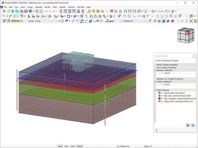
W tym artykule omówiono wyniki analizy geotechnicznej oraz ich graficzne i tabelaryczne przedstawienie w programie RFEM 6.

Wyboczenie giętno-skrętne (LTB) jest zjawiskiem, które występuje, gdy belka lub element konstrukcyjny są zginane, a pas ściskany nie jest wystarczająco podparty bocznie. Prowadzi to do kombinacji przemieszczenia bocznego i skręcenia. Jest to decydujący czynnik przy wymiarowaniu elementów konstrukcyjnych, zwłaszcza smukłych belek i dźwigarów.

W programie RFEM 6 połączenia stalowe definiuje się jako układ elementów. W nowym rozszerzeniu Połączenia stalowe dostępne są podstawowe komponenty do uniwersalnego zastosowania (blachy, spoiny, płaszczyzny pomocnicze). Metody definiowania połączeń opisano w dwóch poprzednich artykułach w Bazie informacji: „Nowe podejście do wymiarowania połączeń stalowych w programie RFEM 6” oraz „Definiowanie elementów połączenia stalowego przy użyciu biblioteki” .

Rozszerzenie Projektowanie konstrukcji aluminiowych dla RFEM 6 wymiaruje pręty aluminiowe ze względu na stan graniczny nośności i użytkowalności zgodnie z Eurokodem 9. Ponadto możliwe jest wymiarowanie zgodnie z ADM 2020 (norma amerykańska).

W tym artykule pokażemy, jak zdefiniować żebra podłużne na blasze pręta za pomocą komponentu „Żebro” w rozszerzeniu Połączenia stalowe.

Zarówno analiza drgań własnych, jak i analiza spektrum odpowiedzi przeprowadzane są na układzie liniowym. Jeżeli w modelu występują nieliniowości, podlega on linearyzacji, dzięki czemu elementy nieliniowe nie są brane pod uwagę w dalszej analizie. Mogą to być na przykład pręty rozciągane, podpory nieliniowe lub przeguby nieliniowe. W tym artykule pokazano, w jaki sposób można nimi zarządzać w analizie dynamicznej.

Jakość analizy statyczno-wytrzymałościowej budynków jest dużo lepsza, gdy można uwzględnić warunki gruntowe w sposób możliwie najbardziej realistyczny. W programie RFEM 6 można realistycznie określić kontur glebowy do analizy za pomocą rozszerzenia Analiza geotechniczna. Ten dodatek można aktywować w danych bazowych modelu, jak pokazano na rysunku 01.
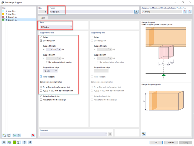
Standardowym rozwiązaniem w konstrukcji prętów drewnianych jest możliwość łączenia mniejszych prętów poprzez podparcie na większym dźwigarze. Dodatkowo warunki na końcach pręta mogą uwzględniać podobną sytuację, w której belka jest oparta na podporze. W obu przypadkach belka musi być zaprojektowana tak, aby uwzględniała nośność w poprzek włókien zgodnie z NDS 2018 s. 3.10.2 i CSA O86:19 punkty 6.5.6 i 7.5.9. W ogólnych programach do projektowania statyczno-wytrzymałościowego zazwyczaj nie jest możliwe przeprowadzenie pełnej kontroli obliczeń, ponieważ powierzchnia docisku jest nieznana. Jednak w programie RFEM 6 nowej generacji i rozszerzeniu Projektowanie konstrukcji drewnianych dodana funkcja "podpór obliczeniowych" umożliwia teraz użytkownikom uwzględnienie docisku NDS i CSA prostopadle do warunków obliczeniowych.

Zrozumienie sztywności połączeń stalowych ma kluczowe znaczenie w projektowaniu konstrukcji. Często połączenia są traktowane jako połączenia całkowicie sztywne lub przegubowe, co może prowadzić do nieekonomicznych lub nawet ryzykownych warunków projektowych. Dowiedz się, w jaki sposób program RFEM firmy Dlubal i rozszerzenie Połączenia stalowe pomagają weryfikować sztywność połączeń i nośność na zginanie, zapewniając bezpieczniejsze i bardziej ekonomiczne warunki projektowe.
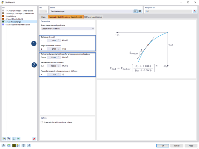
Rozszerzenie Analiza geotechniczna zapewnia programowi RFEM dodatkowe specyficzne modele materiałowe podłoża, które mogą odpowiednio odwzorować złożone zachowanie materiału podłoża. W tym artykule zaprezentujemy, w jaki sposób można określić zależną od naprężeń sztywność modeli materiałowych gruntu.

Ocena przemieszczenia kondygnacji w budynku jest kluczowa dla zapewnienia zadowalających parametrów konstrukcyjnych poprzez ograniczenie przemieszczenia kondygnacji. Nadmierne znoszenie może powodować niestateczność systemu i powodować uszkodzenia elementów niekonstrukcyjnych, takich jak ściany działowe. W tym artykule opisano procedurę wyznaczania przemieszczeń międzykondygnacyjnych zgodnie z ASCE 7-22 i rozszerzeniem Model budynku w programie RFEM 6.

Zaletą modułu dodatkowego RFEM 6 Steel Joints jest możliwość analizy połączeń stalowych przy użyciu modelu MES, dla którego modelowanie przebiega w pełni automatycznie w tle. Elementy składowe złącza stalowego, które kontrolują modelowanie, można wprowadzić, definiując je ręcznie lub korzystając z dostępnych szablonów w bibliotece. Ta ostatnia metoda została opisana w poprzednim artykule z Bazy wiedzy zatytułowanym „Definiowanie komponentów połączenia stalowego przy użyciu biblioteki”. Definiowanie parametrów do wymiarowania połączeń stalowych jest tematem artykułu w bazie wiedzy „Projektowanie połączeń stalowych w RFEM 6”.

Nowa generacja oprogramowania RFEM umożliwia przeprowadzanie obliczeń stateczności zbieżnych prętów drewnianych zgodnie z metodą prętów zastępczych. Zgodnie z tą metodą obliczenia można przeprowadzić, jeżeli spełnione są wytyczne normy DIN 1052, sekcja E8.4.2 dla zmiennych przekrojów. W różnych publikacjach technicznych metoda ta jest również stosowana w przypadku Eurokodu 5. W tym artykule pokazano, jak zastosować metodę prętów zastępczych dla belki dachowej o zbieżnej wysokości.

Jedną z innowacji w programie RFEM 6 jest nowy sposób projektowania połączeń stalowych. W przeciwieństwie do programu RFEM 5, w którym wymiarowanie połączeń stalowych opiera się na rozwiązaniu analitycznym, rozszerzenie Połączenia stalowe w programie RFEM 6 oferuje rozwiązanie dla połączeń stalowych w oparciu o analizę MES.

Z tego artykułu dowiesz się, jak zamodelować proste połączenie z blachą czołową w programie RFEM 6.

W tym artykule przedstawiono model połączenia zakładkowego płatwi ZL na dachu jednospadowym, obliczony w rozszerzeniu Połączenia stalowe i porównany z tabelą nośności podaną przez producenta.
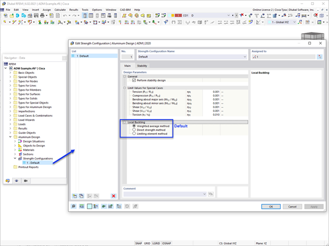
W tym artykule omówiono dostępne opcje określania nominalnej wytrzymałości na zginanie Mnlb dla stanu granicznego wyboczenia lokalnego, podczas projektowania zgodnie z Aluminium Design Manual (Podręcznik projektowania konstrukcji aluminiowych 2020).
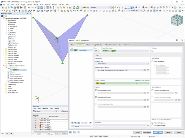
Program RFEM 6 zawiera rozszerzenie Form-Finding do określania kształtów równowagi modeli powierzchni obciążonych rozciąganiem i prętów obciążonych siłami osiowymi. Aktywuj ten dodatek w Danych bazowych modelu i użyj go, aby znaleźć położenie geometryczne, w którym naprężenie wstępne lekkich konstrukcji jest w równowadze z istniejącymi warunkami brzegowymi.

Dzięki rozszerzeniu Połączenia stalowe dla RFEM 6 można tworzyć i analizować połączenia stalowe przy użyciu wydzielonego modelu ES. Modelowanie połączeń można kontrolować poprzez proste i wygodne wprowadzanie elementów. Elementy stalowego połączenia można definiować ręcznie lub przy użyciu szablonów dostępnych w bibliotece. Pierwsza metoda została opisana w poprzednim artykule z Bazy wiedzy zatytułowanym „Nowe podejście do wymiarowania połączeń stalowych w programie RFEM 6”. W tym artykule skupimy się na tej drugiej metodzie; tzn. pokaże, jak definiować komponenty połączenia stalowego przy użyciu szablonów dostępnych w bibliotece programu.