239 Wyniki
Wyświetl wyniki:
Sortuj według:

Dzięki rozszerzeniu Projektowanie konstrukcji stalowych możliwe jest projektowanie konstrukcji stalowych zgodnie z normą AISC 360-22. W poniższym artykule porównano wyniki obliczeń zwichrzenia zgodnie z rozdziałem F z analizą wartości własnych.
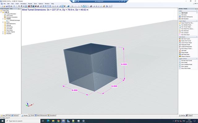
W inżynierii konstrukcyjnej przewidywanie wpływu turbulentnego przepływu wiatru na konstrukcje ma kluczowe znaczenie dla bezpieczeństwa i wydajności. Modelowanie turbulencji w Computational Fluid Dynamics (CFD) pomaga w symulacji tych interakcji. Inżynierowie muszą wybrać praktyczny model turbulencji, równoważąc wydajność, dokładność i możliwości zastosowania. Typowe modele to uśredniony Navier-Stokes (RANS), niestabilny uśredniony Navier-Stokes (URANS) oraz Delayed Detached Eddy Simulation (DDES). Program RANS jest niezawodnym i ekonomicznym rozwiązaniem w przypadku stałych przepływów, URANS rejestruje zależne od czasu zjawiska dla średnich niestateczności, a DDES, hybryda RANS i symulacji dużych wirów (LES), rozwiązuje złożone struktury turbulentne. Zrozumienie mocnych stron i ograniczeń każdego modelu pomoże inżynierom wybrać najlepsze podejście do swoich potrzeb.

Ocena przemieszczenia kondygnacji w budynku jest kluczowa dla zapewnienia zadowalających parametrów konstrukcyjnych poprzez ograniczenie przemieszczenia kondygnacji. Nadmierne znoszenie może powodować niestateczność systemu i powodować uszkodzenia elementów niekonstrukcyjnych, takich jak ściany działowe. W tym artykule opisano procedurę wyznaczania przemieszczeń międzykondygnacyjnych zgodnie z ASCE 7-22 i rozszerzeniem Model budynku w programie RFEM 6.

Blachownica to ekonomiczny wybór w przypadku konstrukcji o dużych rozpiętościach. I-section steel plate girder typically has a deep web to maximize its shear capacity and flange separation, yet thin web to minimize the self-weight. Due to its large height-to-thickness (h/tw) ratio, transverse stiffeners may be required to stiffen the slender web.

Zrozumienie sztywności połączeń stalowych ma kluczowe znaczenie w projektowaniu konstrukcji. Często połączenia są traktowane jako połączenia całkowicie sztywne lub przegubowe, co może prowadzić do nieekonomicznych lub nawet ryzykownych warunków projektowych. Dowiedz się, w jaki sposób program RFEM firmy Dlubal i rozszerzenie Połączenia stalowe pomagają weryfikować sztywność połączeń i nośność na zginanie, zapewniając bezpieczniejsze i bardziej ekonomiczne warunki projektowe.
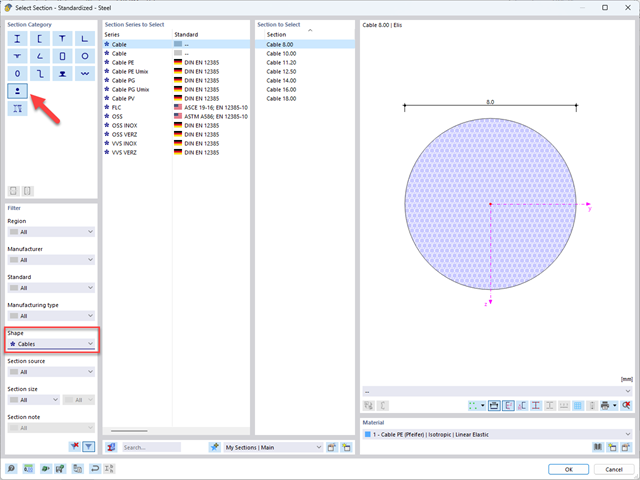
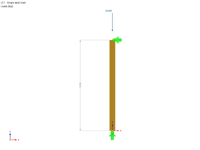
Z tego artykułu dowiesz się, jak modelować i wymiarować konstrukcje kablowe w programach RFEM 6 i RSTAB 9.
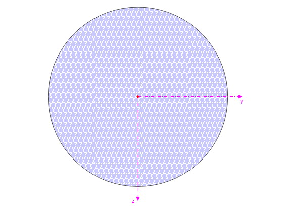
Ten artykuł opisuje i wyjaśnia wpływ sztywności na zginanie kabli na ich siły wewnętrzne. Z tego artykułu dowiesz się również, jak zredukować ten wpływ.

Norma ASCE 7-22 [1], rozdz. 12.9.1.6 określa, kiedy efekty P-delta powinny być uwzględniane podczas przeprowadzania analizy modalnego spektrum odpowiedzi dla obliczeń sejsmicznych. W NBC 2020 [2], Wys. 4.1.8.3.8.c jedynie w niewielkim stopniu wymaga uwzględnienia przechyłów spowodowanych interakcją obciążeń grawitacyjnych z konstrukcją odkształconą. Z tego względu podczas przeprowadzania analizy sejsmicznej mogą wystąpić sytuacje, w których efekty drugiego rzędu, znane również jako P-delta, muszą zostać uwzględnione.

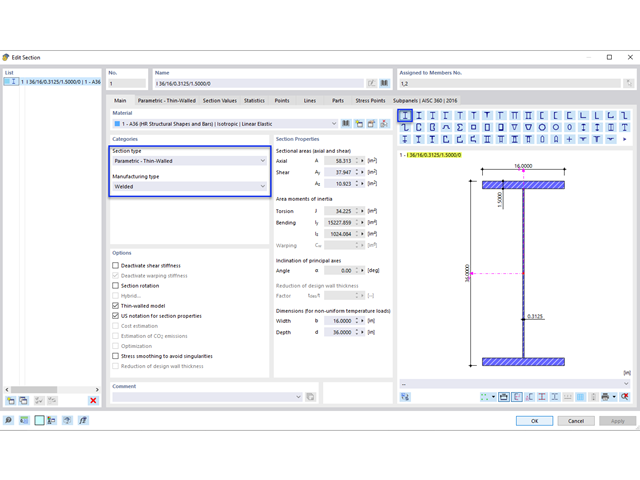
Wyboczenie giętno-skrętne (LTB) jest zjawiskiem, które występuje, gdy belka lub element konstrukcyjny są zginane, a pas ściskany nie jest wystarczająco podparty bocznie. Prowadzi to do kombinacji przemieszczenia bocznego i skręcenia. Jest to decydujący czynnik przy wymiarowaniu elementów konstrukcyjnych, zwłaszcza smukłych belek i dźwigarów.

W rozszerzeniu Projektowanie konstrukcji stalowych dla programu RFEM 6 dostępne są trzy typy ram sprężystych (zwykłe, pośrednie i specjalne). Wyniki obliczeń sejsmicznych zgodnie z AISC 341-22 są podzielone na dwie sekcje: wymagania dotyczące prętów i połączeń.
Rozszerzenie Wymiarowanie drewna umożliwia wymiarowanie słupów drewnianych zgodnie ze standardową metodą ASD 2018 NDS. Dokładne wyznaczenie nośności na ściskanie oraz współczynników redukcyjnych dla prętów drewnianych jest konieczne dla bezpieczeństwa konstrukcji. Poniższy artykuł weryfikuje maksymalną wytrzymałość na wyboczenie krytyczną obliczoną w module rozszerzeniowym Wymiarowanie drewna przy użyciu równań analitycznych krok po kroku zgodnie z normą NDS 2018, w tym współczynników dostosowania przy ściskaniu, skorygowanej wartości obliczeniowej na ściskanie i końcowego stopnia wyboczenia.

Rozszerzenie Projektowanie konstrukcji stalowych w RFEM 6 oferuje teraz możliwość przeprowadzania obliczeń sejsmicznych zgodnie z AISC 341-16 i AISC 341-22. Obecnie dostępnych jest pięć typów systemów sejsmicznych (SFRS).

W rozszerzeniu Projektowanie konstrukcji stalowych dla programu RFEM 6 dostępne są trzy typy ram sprężystych (zwykłe, pośrednie i specjalne). Wyniki obliczeń sejsmicznych zgodnie z AISC 341-16 są podzielone na dwie sekcje: wymagania dotyczące prętów i połączeń.

Obliczanie ramy momentowej zgodnie z AISC 341-16 jest teraz możliwe w rozszerzeniu Projektowanie konstrukcji stalowych dla programu RFEM 6. Wynik obliczeń sejsmicznych jest podzielony na dwie sekcje: wymagania dotyczące prętów i połączeń. W tym artykule omówiono wymaganą wytrzymałość połączenia. Przedstawiono przykładowe porównanie wyników pomiędzy RFEM a AISC Seismic Design Manual.

Obliczenia zwykłej ramy stężonej koncentrycznie (OCBF) oraz SCBF (specjalnej konstrukcji szkieletowej stężonej koncentrycznie) można przeprowadzić w rozszerzeniu Projektowanie konstrukcji stalowych dla programu RFEM 6. Wyniki obliczeń sejsmicznych zgodnie z AISC 341-16 i 341-22 są podzielone na dwie sekcje: Wymagania dotyczące prętów i połączeń.
Stworzenie przykładu walidacyjnego dla obliczeniowej mechaniki płynów (CFD) jest kluczowym krokiem w zapewnieniu dokładności i wiarygodności wyników symulacji. This process involves comparing the outcomes of CFD simulations with experimental or analytical data from real-world scenarios. The objective is to establish that the CFD model can faithfully replicate the physical phenomena it is intended to simulate.
Blachownica to ekonomiczny wybór w przypadku konstrukcji o dużych rozpiętościach. I-section steel plate girder typically has a deep web to maximize its shear capacity and flange separation, yet thin web to minimize the self-weight. Due to its large height-to-thickness (h/tw) ratio, transverse stiffeners may be required to stiffen the slender web.
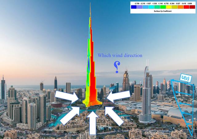
Kierunek wiatru odgrywa kluczową rolę w kształtowaniu wyników symulacji komputerowej mechaniki płynów (CFD) oraz w projektowaniu konstrukcyjnym budynków i infrastruktury. Jest to decydujący czynnik w ocenie interakcji sił wiatru z konstrukcjami, wpływających na rozkład ciśnienia wiatru, a w konsekwencji na reakcje konstrukcji.
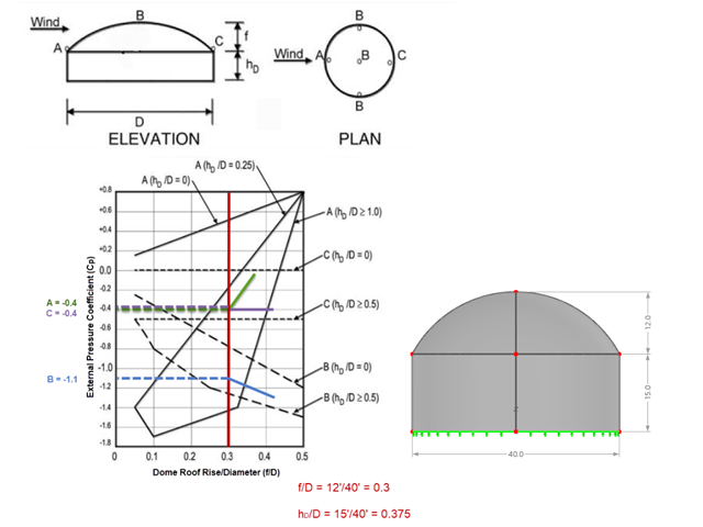
Jeśli chodzi o obciążenia wiatrem konstrukcje budowlane zgodnie z ASCE 7, można znaleźć wiele źródeł, które mogą uzupełnić normy projektowe i pomóc inżynierom w zastosowaniu obciążeń poprzecznych. Jednak inżynierom może być trudniej znaleźć podobne zasoby dla obciążeń wiatrem na konstrukcjach innych niż budynki. W tym artykule omówiono etapy obliczania i przykładania obciążeń wiatrem zgodnie z ASCE 7-22 na okrągłym zbiorniku żelbetowym z dachem w kształcie kopuły.
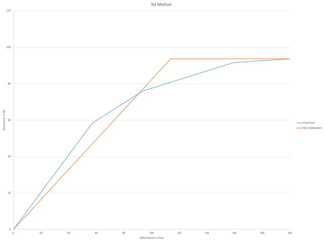
Aby można było przeprowadzić obliczenia push-over, należy zdefiniowaną krzywą nośności przekształcić do postaci uproszczonej. Tak zwana metoda N2 jest opisana w Eurokodzie EN 1998. Ten artykuł powinien pomóc w wyjaśnieniu, co oznacza bilinearyzacja zgodnie z metodą N2.