138 Wyniki
Wyświetl wyniki:
Sortuj według:

Analiza wyboczenia giętnego jest połączeniem analizy stateczności i stanu granicznego nośności, stosowana w konstrukcjach stalowych od setek lat. Punktem wyjścia do rozważenia kwestii stateczności jest krytyczne obciążenie wyboczeniowe, ale dotychczas nie przeprowadzono obliczeń bez uwzględnienia imperfekcji. Jak dokładnie określane są te imperfekcje?

W tym artykule pokażemy, jak zdefiniować żebra podłużne na blasze pręta za pomocą komponentu „Żebro” w rozszerzeniu Połączenia stalowe.

Z tego artykułu dowiesz się, jak zamodelować proste połączenie z blachą czołową w programie RFEM 6.
![Podstawowe kształty konstrukcji membranowych [1]](/pl/webimage/009595/2419506/01-png.png?mw=640&hash=8a9ac87bf3acfb73e6cad970f55eb968a841595c)
Niniejszy artykuł skupia się na specyficznych aspektach projektowania konstrukcji membranowych, które mają specyficzne wymagania, takich jak znajdowanie kształtu (form-finding) i generowanie szablonów cięcia. Integralną częścią projektowania tych konstrukcji jest proces wyszukiwania odpowiednich wstępnie sprężonych kształtów i generowania szablonów cięcia. Tekst krótko opisuje dwa podstawowe procesy w projektowaniu konstrukcji membranowych. Celem jest zilustrowanie ich fizycznego charakteru i zademonstrowanie poszczególnych stwierdzeń za pomocą towarzyszących im przykładów.

Zrozumienie sztywności połączeń stalowych ma kluczowe znaczenie w projektowaniu konstrukcji. Często połączenia są traktowane jako połączenia całkowicie sztywne lub przegubowe, co może prowadzić do nieekonomicznych lub nawet ryzykownych warunków projektowych. Dowiedz się, w jaki sposób program RFEM firmy Dlubal i rozszerzenie Połączenia stalowe pomagają weryfikować sztywność połączeń i nośność na zginanie, zapewniając bezpieczniejsze i bardziej ekonomiczne warunki projektowe.

W artykule przedstawiono podstawowe pojęcia z zakresu dynamiki konstrukcji i ich roli w projektowaniu konstrukcji sejsmicznych. Duży nacisk kładzie się na wyjaśnienie aspektów technicznych w zrozumiały sposób, aby tematyka była zrozumiała dla czytelników bez dużej wiedzy technicznej.

Obliczenia ze względu na zmęczenie zgodnie z EN 1992-1-1 należy przeprowadzać w przypadku elementów konstrukcyjnych, które są poddane działaniu dużych zakresów naprężeń i/lub wielu zmianom obciążenia. W takim przypadku obliczenia dla betonu i zbrojenia są przeprowadzane osobno. Dostępne są dwie alternatywne metody obliczeniowe.

W tym artykule wyjaśniono, jak działają obliczenia podczas wstępnej analizy sztywności w programie Połączenia stalowe.

Obliczanie ramy momentowej zgodnie z AISC 341-16 jest teraz możliwe w rozszerzeniu Projektowanie konstrukcji stalowych dla programu RFEM 6. Wynik obliczeń sejsmicznych jest podzielony na dwie sekcje: wymagania dotyczące prętów i połączeń. W tym artykule omówiono wymaganą wytrzymałość połączenia. Przedstawiono przykładowe porównanie wyników pomiędzy RFEM a AISC Seismic Design Manual.
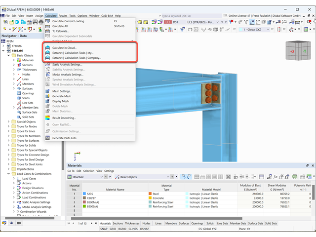
W tym artykule wyjaśniamy, jak działa obliczanie chmury.

W tym artykule przedstawiono model połączenia zakładkowego płatwi ZL na dachu jednospadowym, obliczony w rozszerzeniu Połączenia stalowe i porównany z tabelą nośności podaną przez producenta.

Zarówno analiza drgań własnych, jak i analiza spektrum odpowiedzi przeprowadzane są na układzie liniowym. Jeżeli w modelu występują nieliniowości, podlega on linearyzacji, dzięki czemu elementy nieliniowe nie są brane pod uwagę w dalszej analizie. Mogą to być na przykład pręty rozciągane, podpory nieliniowe lub przeguby nieliniowe. W tym artykule pokazano, w jaki sposób można nimi zarządzać w analizie dynamicznej.
Zgodność z przepisami budowlanymi, takimi jak Eurokod, jest niezbędna dla zapewnienia bezpieczeństwa, integralności konstrukcji i trwałości budynków i konstrukcji. Obliczeniowa mechanika płynów (CFD) odgrywa istotną rolę w tym procesie, symulując zachowanie płynów, optymalizując projekty i pomagając architektom i inżynierom w spełnieniu wymagań Eurokodu związanych z analizą obciążenia wiatrem, wentylacją naturalną, bezpieczeństwem pożarowym i efektywnością energetyczną. Integrując CFD z procesem projektowania, profesjonaliści mogą tworzyć bezpieczniejsze, wydajniejsze i zgodne z przepisami budynki, które spełniają najwyższe standardy konstrukcyjne i projektowe w Europie.
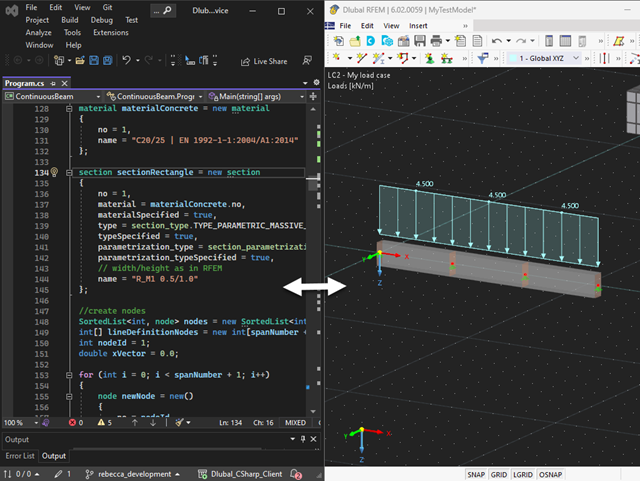
Nasza usługa sieciowa oferuje użytkownikom możliwość komunikacji z programami RFEM 6 i RSTAB 9 za pomocą różnych języków programowania. Funkcje wysokiego poziomu (HLF) firmy Dlubal umożliwiają rozszerzenie i uproszczenie funkcjonalności WebService. Zgodnie z RFEM 6 i RSTAB 9, korzystanie z naszego webservice sprawia, że praca inżyniera jest łatwiejsza i szybsza. Wypróbuj teraz! Ten samouczek pokazuje, jak korzystać z biblioteki C #na prostym przykładzie.
Połączenia stalowe w programie RFEM 6 można tworzyć poprzez wprowadzenie wstępnie zdefiniowanych komponentów w rozszerzeniu Połączenia stalowe. Lista tych elementów jest stale rozszerzana, aby ułatwić modelowanie połączeń stalowych. W tym artykule przedstawiamy blachę łączącą, która została niedawno dodana do biblioteki rozszerzenia.
,_Table_22.5.5.1_ACI_318-19.png?mw=640&hash=7e50d54e01238943fe1c691c0aa197d9b2fa8511)
W najnowszej normie ACI 318-19 długoterminowa zależność w określaniu nośności betonu na ścinanieVc zostaje przedefiniowana. Dzięki nowej metodzie wysokość pręta, stopień zbrojenia podłużnego i naprężenie normalne wpływają teraz na wytrzymałość na ścinanie Vc. W poniższym artykule opisano zaktualizowane podejście do obliczeń dla ścinania, a zastosowanie przedstawiono na przykładzie.
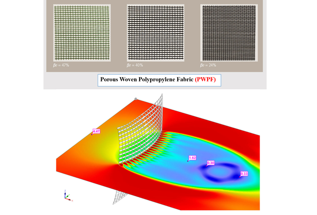
W obliczeniowej mechanice płynów (CFD) można modelować złożone powierzchnie, które nie są całkowicie stałe, używając porowatego i przepuszczalnego medium. W świecie rzeczywistym mogą to być na przykład wiatrochrony, siatki druciane, perforowane fasady i okładziny, żaluzje, przęsła (stosy poziomych walców) i tak dalej.
Programy do arkuszy kalkulacyjnych, takie jak EXCEL, są popularne wśród inżynierów, ponieważ można z łatwością zautomatyzować obliczenia i szybko uzyskać wyniki. Połączenie programu MS EXCEL jako graficznego interfejsu użytkownika z WebService API jest zatem oczywiste. Za pomocą bezpłatnej biblioteki xlwings dla Pythona można sterować programem EXCEL oraz odczytywać i zapisywać wartości. Funkcjonalność tę wyjaśniono poniżej na przykładzie.

Osłony przeciwwiatrowe to specjalne konstrukcje tekstylne, które mają za zadanie chronić środowisko przed szkodliwymi cząsteczkami chemicznymi, jak również ograniczać erozję wietrzną, przyczyniając się do ochrony cennych zasobów. RFEM i RWIND są używane do analizy konstrukcji wiatrowej dla jednostronnej interakcji płyn-konstrukcja (FSI).
W tym artykule pokazano, jak wymiarować osłony przeciwwiatrowe przy użyciu programów RFEM i RWIND.
W tym artykule pokazano, jak wymiarować osłony przeciwwiatrowe przy użyciu programów RFEM i RWIND.
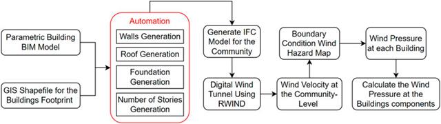
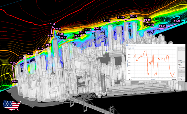
W artykule tym opracowano nowatorskie podejście do generowania modeli CFD na poziomie miejscowości poprzez połączenie modelowania informacji o budynku (BIM) i systemów informacji geograficznej (GIS) w celu zautomatyzowania generowania trójwymiarowego modelu terenu o wysokiej rozdzielczości, który zostanie wykorzystany jako dane wejściowe dla cyfrowego tunelu aerodynamicznego z wykorzystaniem RWIND.
RWIND 2 to program do generowania obciążeń wiatrem w oparciu o CFD (Computational Fluid Dynamics). Symulacja numeryczna przepływu wiatru jest generowana wokół dowolnego budynku, w tym budynku o nieregularnej lub unikalnej geometrii, w celu określenia obciążeń wiatrem na powierzchnie i pręty. RWIND 2 może być zintegrowany z programem RFEM/RSTAB w celu przeprowadzenia analizy statyczno-wytrzymałościowej lub jako samodzielna aplikacja.
API dla RFEM 6, RSTAB 9 i RSECTION opiera się na koncepcji usług sieciowych (Webservice). Aby zapoznać się z tematem, w poniższym artykule omawiamy kolejny przykład w języku C#.
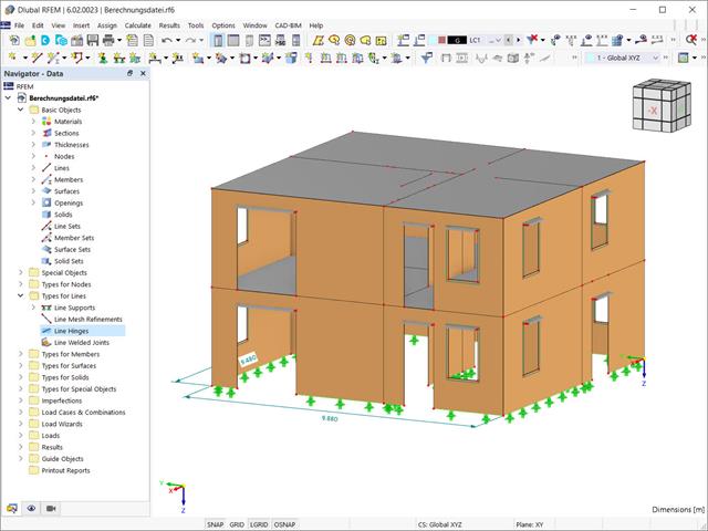
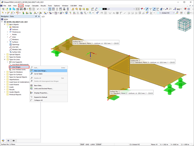
Przy użyciu specjalnego przegubu liniowego dostępnego w programie RFEM 6 można poprawnie uwzględnić podczas modelowania właściwości połączenia płyty żelbetowej ze ścianą murowaną. Z tego artykułu dowiesz się, jak zdefiniować ten typ przegubu na praktycznym przykładzie.
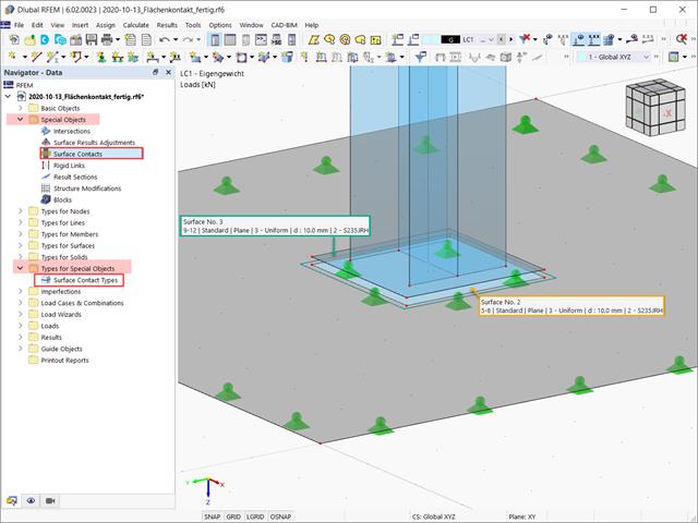
W tym artykule opisano, jak tworzyć kontakty między dwiema lub większą liczbą równoległych powierzchni poprzez kontrolowanie przenoszenia sił między nimi.
W tym artykule pokażemy, jak prawidłowo uwzględnić połączenie między powierzchniami stykającymi się na jednej linii za pomocą przegubów liniowych w programie RFEM 6.
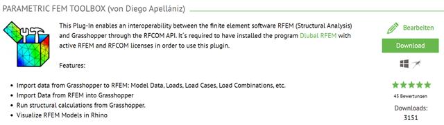
W tym artykule opisano rozwój Parametric FEM Toolbox i niektóre z możliwych przepływów pracy przy użyciu tego nowego narzędzia.
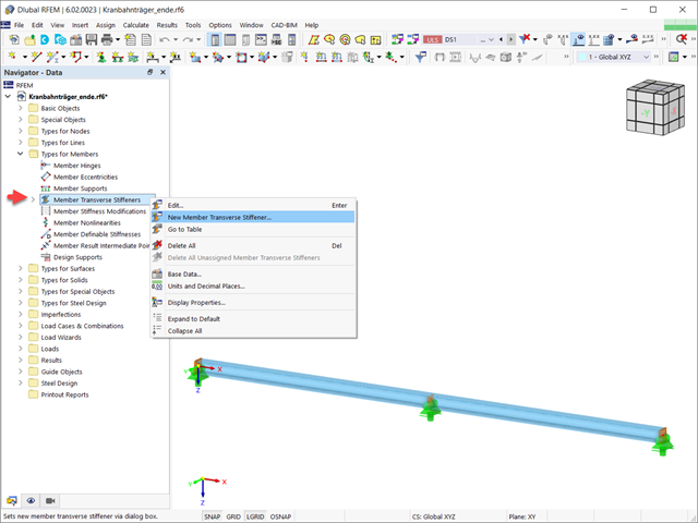
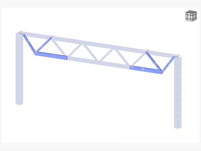
W tym artykule pokazano, jak definiować różne typy usztywnień poprzecznych pręta w programie RFEM 6 i RSTAB 9. Pokazano tu również, w jaki sposób uwzględnić je w projektowaniu i obliczeniach prętów o 7 stopniach swobody.

W programie RFEM 6 możliwe jest definiowanie spoin liniowych na liniach między powierzchniami i obliczanie naprężeń w spoinie za pomocą rozszerzenia Analiza naprężeniowo-odkształceniowa. Z tego artykułu dowiesz się, jak to zrobić.
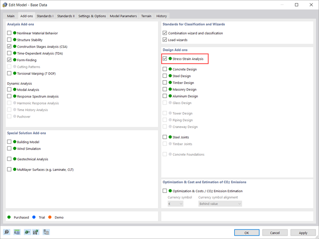
W tym artykule pokazano, jak zarządzać danymi wejściowymi dla konfiguracji obliczeń prętów i powierzchni w rozszerzeniu Analiza naprężeniowo-odkształceniowa.
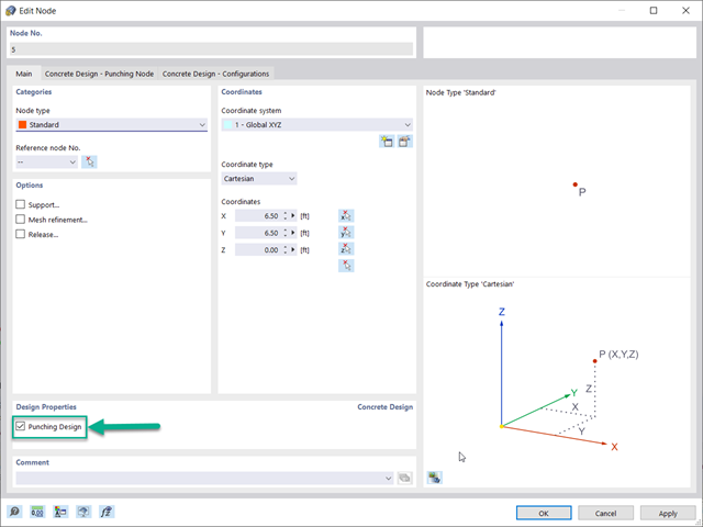
Optymalnym scenariuszem, w którym należy zastosować obliczenia wytrzymałości na przebicie, zgodnie z ACI 318-19 lub CSA A23.3:19, jest sytuacja, w której w płycie występuje duża koncentracja obciążeń lub sił reakcji występujących w jednym węźle. W programie RFEM 6 węzeł, w którym występuje przebicie, nazywany jest węzłem z przebiciem. Przyczyny tak dużej koncentracji sił mogą być spowodowane przez słup, siłę skupioną lub podporę węzłową. Łączenie ścian może również powodować obciążenia skupione na końcach, narożach i na końcach obciążeń liniowych i podpór.