204 Wyniki
Wyświetl wyniki:
Sortuj według:

Niniejszy artykuł dotyczy długotrwałego ugięcia konstrukcji betonowych zgodnie z ACI 318 i CSA A23.3.

Podczas obliczania siły tnącej w programie Wymiarowanie betonu zbrojonego, działającą siłę tnącą Vz można zredukować zgodnie z EN 1992-1-1. Poniższy artykuł opisuje redukcję siły tnącej od obciążeń skupionych w pobliżu podpory oraz wymiarowanie sił tnących w odległości d od krawędzi podpory w przypadku obciążenia równomiernie rozłożonego.

Każdego dnia tysiące inżynierów konstrukcyjnych projektują elementy konstrukcyjne, korzystając z wzorów kontroli projektu, uwzględniających krytyczne obciążenie wyboczeniowe. Ale skąd wzięły się te starożytne wzory, które opracował ponad 200 lat temu i które stanowią podstawę wszystkich trzech koncepcji projektowania konstrukcji stalowych?

W tym artykule nakreślono analogię między generowaniem siatki ES dla osobnych obiektów za pomocą opcji “Preferowana niezależna siatka ES” a generowaniem siatki bez korzystania z tej opcji.

Dzięki rozszerzeniu Projektowanie konstrukcji stalowych możliwe jest projektowanie konstrukcji stalowych zgodnie z normą AISC 360-22. W poniższym artykule porównano wyniki obliczeń zwichrzenia zgodnie z rozdziałem F z analizą wartości własnych.
![Podstawowe kształty konstrukcji membranowych [1]](/pl/webimage/009595/2419506/01-png.png?mw=640&hash=8a9ac87bf3acfb73e6cad970f55eb968a841595c)
Niniejszy artykuł skupia się na specyficznych aspektach projektowania konstrukcji membranowych, które mają specyficzne wymagania, takich jak znajdowanie kształtu (form-finding) i generowanie szablonów cięcia. Integralną częścią projektowania tych konstrukcji jest proces wyszukiwania odpowiednich wstępnie sprężonych kształtów i generowania szablonów cięcia. Tekst krótko opisuje dwa podstawowe procesy w projektowaniu konstrukcji membranowych. Celem jest zilustrowanie ich fizycznego charakteru i zademonstrowanie poszczególnych stwierdzeń za pomocą towarzyszących im przykładów.
W inżynierii konstrukcyjnej przewidywanie wpływu turbulentnego przepływu wiatru na konstrukcje ma kluczowe znaczenie dla bezpieczeństwa i wydajności. Modelowanie turbulencji w Computational Fluid Dynamics (CFD) pomaga w symulacji tych interakcji. Inżynierowie muszą wybrać praktyczny model turbulencji, równoważąc wydajność, dokładność i możliwości zastosowania. Typowe modele to uśredniony Navier-Stokes (RANS), niestabilny uśredniony Navier-Stokes (URANS) oraz Delayed Detached Eddy Simulation (DDES). Program RANS jest niezawodnym i ekonomicznym rozwiązaniem w przypadku stałych przepływów, URANS rejestruje zależne od czasu zjawiska dla średnich niestateczności, a DDES, hybryda RANS i symulacji dużych wirów (LES), rozwiązuje złożone struktury turbulentne. Zrozumienie mocnych stron i ograniczeń każdego modelu pomoże inżynierom wybrać najlepsze podejście do swoich potrzeb.

Zrozumienie sztywności połączeń stalowych ma kluczowe znaczenie w projektowaniu konstrukcji. Często połączenia są traktowane jako połączenia całkowicie sztywne lub przegubowe, co może prowadzić do nieekonomicznych lub nawet ryzykownych warunków projektowych. Dowiedz się, w jaki sposób program RFEM firmy Dlubal i rozszerzenie Połączenia stalowe pomagają weryfikować sztywność połączeń i nośność na zginanie, zapewniając bezpieczniejsze i bardziej ekonomiczne warunki projektowe.

Wyboczenie giętno-skrętne (LTB) jest zjawiskiem, które występuje, gdy belka lub element konstrukcyjny są zginane, a pas ściskany nie jest wystarczająco podparty bocznie. Prowadzi to do kombinacji przemieszczenia bocznego i skręcenia. Jest to decydujący czynnik przy wymiarowaniu elementów konstrukcyjnych, zwłaszcza smukłych belek i dźwigarów.
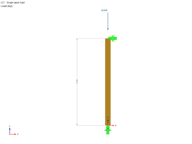
Rozszerzenie Wymiarowanie drewna umożliwia wymiarowanie słupów drewnianych zgodnie ze standardową metodą ASD 2018 NDS. Dokładne wyznaczenie nośności na ściskanie oraz współczynników redukcyjnych dla prętów drewnianych jest konieczne dla bezpieczeństwa konstrukcji. Poniższy artykuł weryfikuje maksymalną wytrzymałość na wyboczenie krytyczną obliczoną w module rozszerzeniowym Wymiarowanie drewna przy użyciu równań analitycznych krok po kroku zgodnie z normą NDS 2018, w tym współczynników dostosowania przy ściskaniu, skorygowanej wartości obliczeniowej na ściskanie i końcowego stopnia wyboczenia.

Obliczenia ze względu na zmęczenie zgodnie z EN 1992-1-1 należy przeprowadzać w przypadku elementów konstrukcyjnych, które są poddane działaniu dużych zakresów naprężeń i/lub wielu zmianom obciążenia. W takim przypadku obliczenia dla betonu i zbrojenia są przeprowadzane osobno. Dostępne są dwie alternatywne metody obliczeniowe.
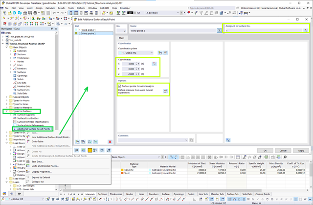
Jeśli dostępne są wyniki parcia powierzchniowego na budynek wywołane wiatrem, można je zastosować w modelu konstrukcyjnym w programie RFEM 6, przetworzonym przez RWIND 2 i wykorzystać jako obciążenia wiatrem do analizy statycznej w RFEM 6.

Obliczanie ramy momentowej zgodnie z AISC 341-16 jest teraz możliwe w rozszerzeniu Projektowanie konstrukcji stalowych dla programu RFEM 6. Wynik obliczeń sejsmicznych jest podzielony na dwie sekcje: wymagania dotyczące prętów i połączeń. W tym artykule omówiono wymaganą wytrzymałość połączenia. Przedstawiono przykładowe porównanie wyników pomiędzy RFEM a AISC Seismic Design Manual.
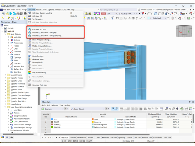
W tym artykule wyjaśniamy, jak działa obliczanie chmury.
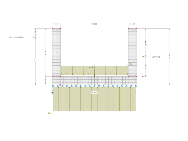
Ten przykład pokazuje, jak szybko określić w programie RFEM wyporność lub stan graniczny wyporności dla kontenera.
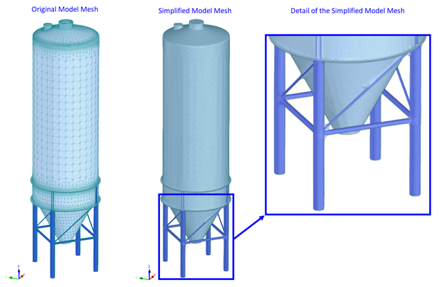
Obliczenia CFD są na ogół bardzo złożone. Dokładne obliczenia przepływu wiatru wokół skomplikowanych konstrukcji są bardzo czasochłonne i kosztowne. W wielu zastosowaniach inżynierskich wysoka dokładność nie jest wymagana, a nasz program CFD RWIND 2 pozwala w takich przypadkach uprościć model konstrukcji i znacznie zredukować koszty. W tym artykule odpowiedzi na niektóre pytania dotyczące uproszczenia.

W tym artykule przedstawiono model połączenia zakładkowego płatwi ZL na dachu jednospadowym, obliczony w rozszerzeniu Połączenia stalowe i porównany z tabelą nośności podaną przez producenta.
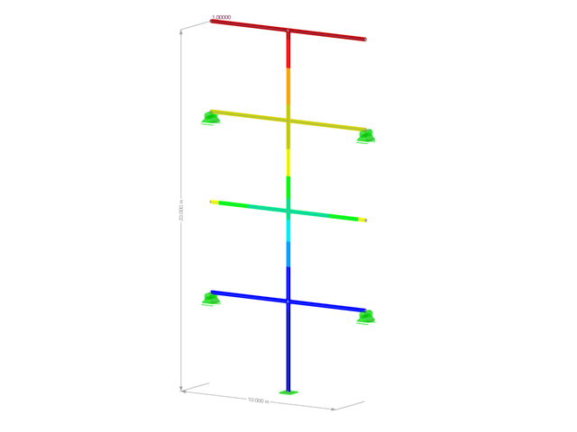
Analiza spektrum odpowiedzi jest jedną z najczęściej stosowanych metod obliczeniowych w przypadku obciążenia trzęsieniem ziemi. Metoda ta ma wiele zalet, a najważniejsza z nich to możliwość znacznego uproszczenia obliczeń. Skomplikowany charakter obciążenia jakim jest trzęsienie ziemi jest upraszczany do postaci, która umożliwia przeprowadzenie analizy o rozsądnym stopniu pracochłonności. Wadą metody jest natomiast to, że w wyniku tego uproszczenia traci się część informacji o obciążeniu. Sposobem na zniwelowanie tego ograniczenia może być zastosowanie równoważnej kombinacji liniowej podczas łączenia odpowiedzi modalnych. W poniższym artykule wyjaśniono to bardziej szczegółowo na konkretnym przykładzie.
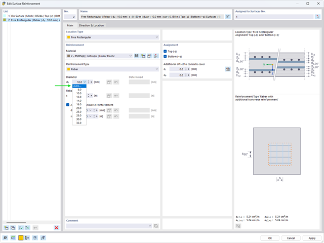
Automatyczny proces wymiarowania zbrojenia określa zbrojenie powierzchniowe, które zapewnia wymaganą ilość zbrojenia wynikającego z obliczeń.
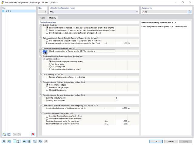
Jeżeli na górnej półce znajduje się płyta betonowa, działa ona jak podpora boczna (konstrukcja zespolona) i zapobiega problemom ze statecznością przy wyboczeniu skrętnym. Jeżeli moment zginający jest ujemny, dolna półka jest obciążona, a górna rozciągana. Jeżeli podparcie boczne nie jest wystarczające ze względu na sztywność środnika, kąt pomiędzy dolną półką a linią nacięcia środnika jest zmienny, przez co istnieje możliwość wystąpienia niestateczności wymiarowej dolnej półki.
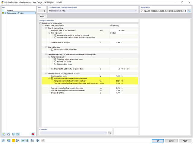
Rozszerzenie Projektowanie konstrukcji stalowych umożliwia wymiarowanie stalowych elementów konstrukcyjnych na wypadek pożaru, z zastosowaniem prostych metod obliczeniowych, zgodnie z Eurokodem 3. Temperatura elementu w chwili wykrycia może być określana automatycznie na podstawie krzywych temperatura-czas określonych w normie. Oprócz uwzględnienia okładzin przeciwpożarowych można również wziąć pod uwagę korzystne właściwości cynkowania ogniowego.
Program RFEM 6 oferuje rozszerzenie Wymiarowanie aluminium do wymiarowania prętów aluminiowych. W tym artykule pokazano, jak w programie obliczane są przekroje klasy 4 zgodnie z Eurokodem 9.
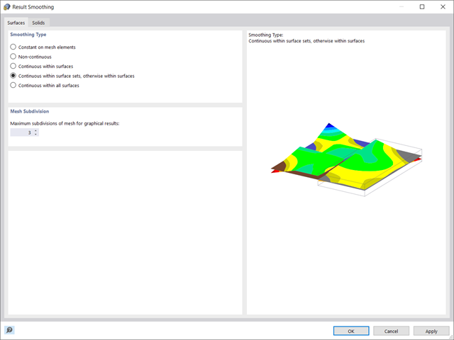
W programie RFEM 6 wyniki dla węzłów siatki ES są określane przy użyciu metody elementów skończonych. Aby rozkład sił wewnętrznych, odkształceń i naprężeń był ciągły, wartości węzłowe są uśredniane w procesie interpolacji. W tym artykule przedstawimy i porównamy różne typy uśredniania, które w tym celu można zastosować.
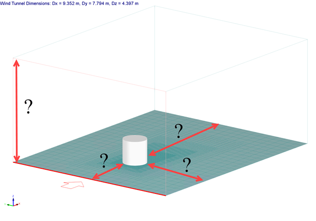
Rozmiar domeny obliczeniowej (rozmiar tunelu aerodynamicznego) jest ważnym aspektem symulacji wiatru, który ma znaczący wpływ na dokładność, a także na koszt symulacji CFD.
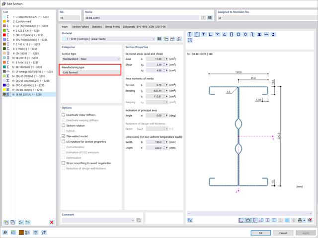
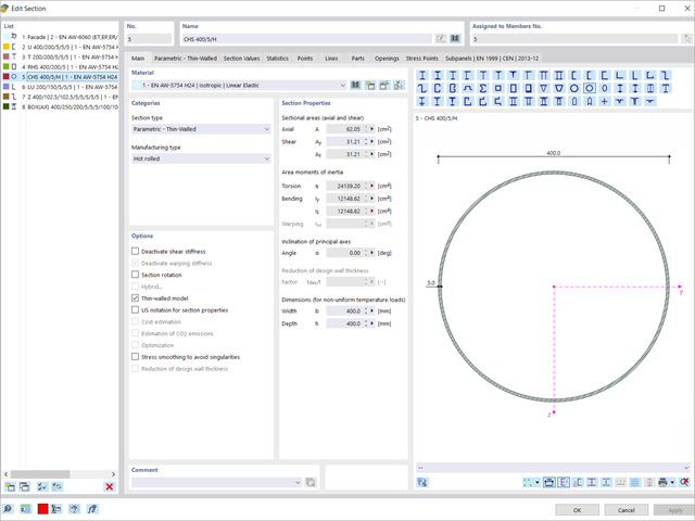
W tym artykule przedstawiono wymiarowanie przekrojów stalowych formowanych na zimno zgodnie z EN 1993-1-3, sekcja 6.1.6 w programie RFEM 6. Ponieważ temat jest nadal rozwijany, przedstawione zostaną aktualnie dostępne opcje.
,_Table_22.5.5.1_ACI_318-19.png?mw=640&hash=7e50d54e01238943fe1c691c0aa197d9b2fa8511)
W najnowszej normie ACI 318-19 długoterminowa zależność w określaniu nośności betonu na ścinanieVc zostaje przedefiniowana. Dzięki nowej metodzie wysokość pręta, stopień zbrojenia podłużnego i naprężenie normalne wpływają teraz na wytrzymałość na ścinanie Vc. W poniższym artykule opisano zaktualizowane podejście do obliczeń dla ścinania, a zastosowanie przedstawiono na przykładzie.

Niniejszy artykuł jest związany z trwającym projektem, w ramach którego opracowywany i wdrażany jest cyfrowy bliźniak konstrukcyjny mostu Kalix w Szwecji.
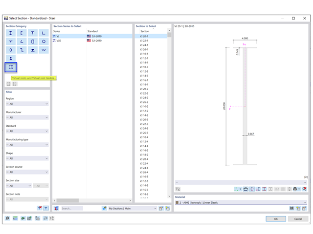
Steel Joist Institute (SJI) wcześniej opracował tabele wirtualnych belek nośnych w celu oszacowania właściwości przekroju dla belek stalowych z otwartym środnikiem. Te przekroje belek wirtualnych są scharakteryzowane jako równoważne belki o szerokich półkach, które są bardzo zbliżone do pola powierzchni pasa, efektywnego momentu bezwładności i ciężaru. Wirtualne belki nośne są również dostępne w bazie danych przekrojów w programach RFEM i RSTAB.
RWIND 2 to program do generowania obciążeń wiatrem w oparciu o CFD (Computational Fluid Dynamics). Symulacja numeryczna przepływu wiatru jest generowana wokół dowolnego budynku, w tym budynku o nieregularnej lub unikalnej geometrii, w celu określenia obciążeń wiatrem na powierzchnie i pręty. RWIND 2 może być zintegrowany z programem RFEM/RSTAB w celu przeprowadzenia analizy statyczno-wytrzymałościowej lub jako samodzielna aplikacja.
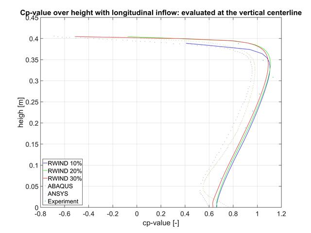
W tym artykule porównujemy wyniki z programów RWIND, ABAQUS i ANSYS z badaniem w tunelu aerodynamicznym przy użyciu prostego geometrycznie modelu.