85 Wyniki
Wyświetl wyniki:
Sortuj według:

- 002129
- Ogólne informacje
- Projektowanie konstrukcji stalowych RFEM 6
- Projektowanie konstrukcji stalowych RSTAB 9
- Szeroki wybór dostępnych przekrojów, takich jak dwuteowniki walcowane; ceowniki; teowniki; kątowniki; profile zamknięte prostokątne i okrągłe; pręty okrągłe; przekroje symetryczne i niesymetryczne, parametryczne przekroje dwuteowe, teowe, kątowniki; przekroje złożone (przydatność do obliczeń zależy od wybranej normy)
- Wymiarowanie ogólnych przekrojów RSECTION (w zależności od formatów obliczeniowych dostępnych w odpowiedniej normie); na przykład obliczanie naprężeń zastępczych
- Wymiarowanie prętów o zbieżnym przekroju (metoda zależna od normy)
- Możliwe jest dostosowanie istotnych współczynników obliczeniowych i parametrów normowych
- Elastyczność dzięki szczegółowym opcjom ustawień dla podstawy i zakresu obliczeń
- Szybkie i przejrzyste wyświetlanie wyników dla globalnej oceny ich rozkładu na konstrukcji po zakończeniu obliczeń
- Szczegółowe wyniki obliczeń i niezbędne wzory (jasna i łatwa do zweryfikowania ścieżka wyników)
- Przejrzyste zestawienie wyników w formie numerycznej w stosownych oknach oraz możliwość ich graficznego przedstawienia na konstrukcji
- Integracja wyników z protokołem wydruku programu RFEM/RSTAB
- 002130
- Ogólne informacje
- Projektowanie konstrukcji stalowych RFEM 6
- Projektowanie konstrukcji stalowych RSTAB 9
- Wymiarowanie elementów rozciąganych, ściskanych, zginanych, ścinanych, skręcanych i poddanych połączonemu działaniu tych sił wewnętrznych
- Obliczanie rozciągania z uwzględnieniem zredukowanej powierzchni przekroju (np. osłabienie z uwagi na otwory)
- Automatyczna klasyfikacja przekrojów w celu sprawdzenia wyboczenia lokalnego
- Siły wewnętrzne z obliczeń ze skręcaniem skrępowanym (7 stopni swobody) są uwzględniane w kontroli naprężeń zastępczych (obecnie nie dla norm projektowych AISC 360-16 i GB 50017).
- Wymiarowanie przekrojów klasy 4 o właściwościach efektywnych zgodnie z EN 1993-1-5 oraz przekrojów formowanych na zimno zgodnie z EN 1993-1-3, AISI S100 lub CSA S136 (licencje dla RSECTION i "Przekroje efektywne" " są wymagane dla przekrojów RSECTION)
- Sprawdzenie wyboczenia przy ścinaniu zgodnie z EN 1993-1-5 z uwzględnieniem usztywnień poprzecznych
- Wymiarowanie elementów ze stali nierdzewnej zgodnie z EN 1993‑1-4
- 002131
- Obliczenia
- Projektowanie konstrukcji stalowych RFEM 6
- Projektowanie konstrukcji stalowych RSTAB 9
- Analiza stateczności dla wyboczenia giętnego, wyboczenia skrętnego i wyboczenia giętno-skrętnego przy ściskaniu
- Import długości efektywnych z obliczeń przy użyciu rozszerzenia Stateczność konstrukcji
- Graficzne wprowadzanie i kontrola zdefiniowanych podpór węzłowych oraz długości efektywnych w celu analizy stateczności
- Analiza zwichrzenia elementów poddanych obciążeniu momentem
- W zależności od normy istnieje wybór między wprowadzaniem wartości Mcr przez użytkownika, metodą analityczną z normy lub wykorzystaniem wewnętrznego solwera wartości własnych
- Uwzględnienie panelu usztywniającego i ograniczenia obrotu podczas korzystania z solwera wartości własnych
- Graficzne przedstawienie postaci własnej w przypadku zastosowania solwera wartości własnych
- Analiza stateczności elementów konstrukcyjnych ze ściskaniem i naprężeniem zginającym, w zależności od normy obliczeniowej
- Przejrzyste obliczenia wszystkich niezbędnych współczynników, takich jak współczynniki uwzględniające rozkładu momentów lub współczynniki interakcji
- Alternatywne uwzględnienie wszystkich wpływów dla analizy stateczności podczas określania sił wewnętrznych w programie RFEM/RSTAB (analiza drugiego rzędu, imperfekcje, redukcja sztywności, ewentualnie w połączeniu z rozszerzeniem Skręcanie skrępowane (7 stopni swobody))

- 002132
- Wyniki
- Projektowanie konstrukcji stalowych RFEM 6
- Projektowanie konstrukcji stalowych RSTAB 9
Układ konstrukcyjny należy wprowadzić i obliczyć siły wewnętrzne w programach RFEM i RSTAB. Użytkownik ma pełny dostęp do obszernych bibliotek materiałów i przekrojów. Masz pytania dotyczące programu? W programie RSECTION można również tworzyć przekroje ogólne.
Projektowanie konstrukcji stalowych jest w pełni zintegrowane z programami głównymi. Uwzględniają one automatycznie konstrukcję i dostępne wyniki obliczeń. Do wymiarowania konstrukcji aluminiowych można przydzielić dodatkowe dane, takie jak długości efektywne, redukcje przekroju lub parametry obliczeniowe. W wielu miejscach programu można łatwo wybrać elementy graficznie za pomocą funkcji [Wybierz].

- 002304
- Ogólne informacje
- Projektowanie konstrukcji stalowych RFEM 6
- Projektowanie konstrukcji stalowych RSTAB 9
- W przypadku obliczeń zgodnie z Eurokodem 3 parametry załączników krajowych (NA) są zintegrowane dla następujących krajów:
-
 DIN EN 1993-1-1/NA:2016-04 (Niemcy)
 -
 ÖNORM EN 1993-1-1/NA:2015-12 (Austria)
 -
 SN EN 1993-1-1/NA:2016-07 (Szwajcaria)
 -
 BDS EN 1993-1-1/NA:2015-10 (Bułgaria)
 -
 BS EN 1993-1-1/NA:2016-07 (Wielka Brytania)
 -
 CEN EN 1993-1-1/2015-06 (Unia Europejska)
 -
 CYS EN 1993-1-1/NA:2015-07 (Cypr)
 -
 CZE EN 1993-1-1/NA:2016-06 (Republika Czeska)
 -
 DS EN 1993-1-1/NA:2015-07 (Dania)
 -
 ELOT EN 1993-1-1/NA:2017-01 (Grecja)
 -
 EVS EN 1993-1-1/NA:2015-08 (Estonia)
 -
 HRN EN 1993-1-1/NA:2016-03 (Chorwacja)
 -
 I S. EN 1993-1-1/NA:2016-03 (Irlandia)
 -
 ILNAS EN 1993-1-1/NA:2015-06 (Luksemburg)
 -
 IST EN 1993-1-1/NA:2015-11 (Islandia)
 -
 LST EN 1993-1-1/NA:2017-01 (Litwa)
 -
 LVS EN 1993-1-1/NA:2015-10 (Łotwa)
 -
 MS EN 1993-1-1/NA:2010-01 (Malezja)
 -
 MSZ EN 1993-1-1/NA:2015-11 (Węgry)
 -
 NBN EN 1993-1-1/NA:2015-07 (Belgia)
 -
 NEN EN 1993-1-1/NA:2016-12 (Holandia)
 -
 NF EN 1993-1-1/NA:2016-02 (Francja)
 -
 NP EN 1993-1-1/NA:2009-03 (Portugalia)
 -
 NS EN 1993-1-1/NA:2015-09 (Norwegia)
 -
 PN EN 1993-1-1/NA:2015-08 (Polska)
 -
 SFS EN 1993-1-1/NA:2015-08 (Finlandia)
 -
 SIST EN 1993-1-1/NA:2016-09 (Słowenia)
 -
 SR EN 1993-1-1/NA:2016-04 (Rumunia)
 -
 SS EN 1993-1-1/NA:2019-05 (Singapur)
 -
 SS EN 1993-1-1/NA:2015-06 (Szwecja)
 -
 STN EN 1993-1-1/NA:2015-10 (Słowacja)
 -
 TKP EN 1993-1-1/NA:2015-04 (Białoruś)
 -
 UNE EN 1993-1-1/NA:2016-02 (Hiszpania)
 -
 UNI EN 1993-1-1/NA:2015-08 (Włochy)
-
- W obliczeniach zgodnie z amerykańską normą AISC 360 uwzględniono następujące metody analizy:
-
 Obliczenia współczynnika obciążenia i odporności (LRFD)
 -
Projektowanie dopuszczalnych naprężeń (ASD)
-
- 002336
- Wyniki
- Projektowanie konstrukcji stalowych RFEM 6
- Projektowanie konstrukcji stalowych RSTAB 9
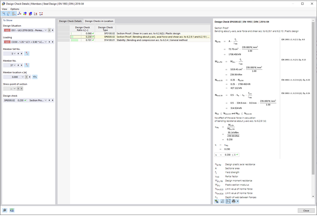
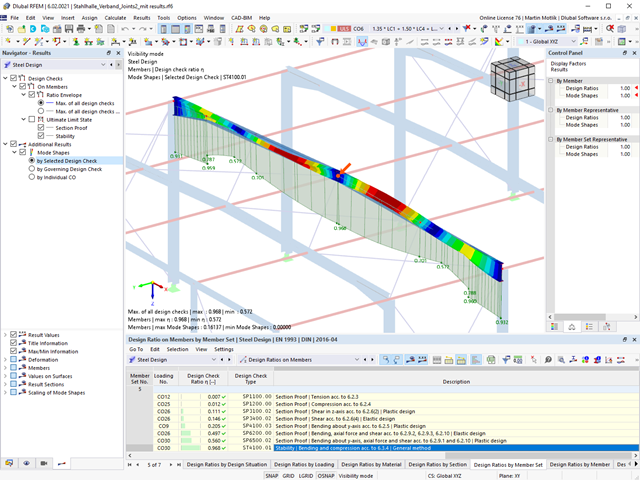
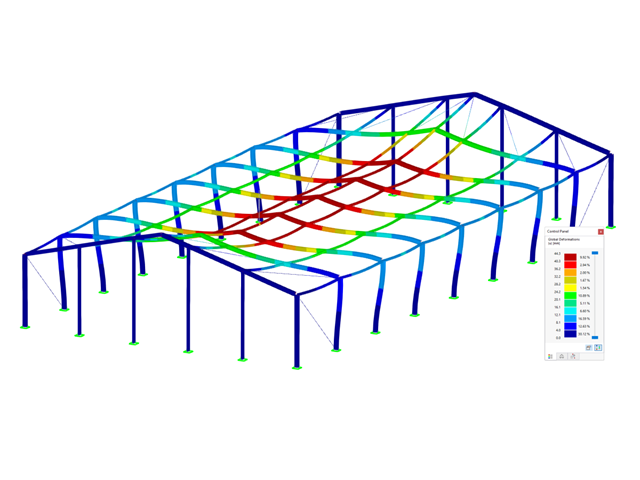
Czy projekt zakończył się sukcesem? Usiądź wygodnie i zrelaksuj się. Przeprowadzone kontrole obliczeń są wyświetlane w tabelach. Wszystkie szczegóły wyników są wyświetlane i można je łatwo śledzić dzięki przejrzyście ułożonym wzorom obliczeniowym.
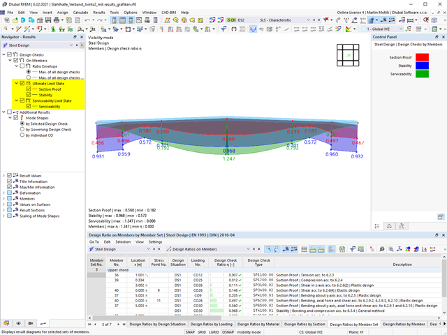
Weryfikacje są przeprowadzane we wszystkich decydujących miejscach prętów. Wykres wyników dostępny jest w postaci graficznej. Ponadto, użytkownik ma dostęp do szczegółowych grafik, takich jak rozkład naprężeń w przekroju lub decydujący kształt drgań własnych, dostępnych w wynikach.
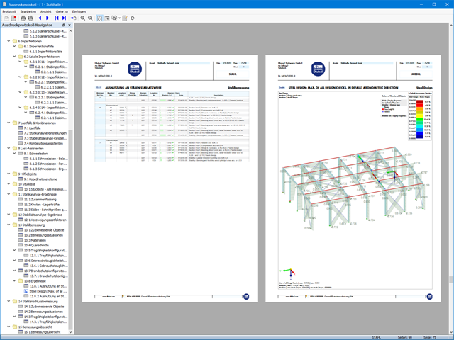
Wszystkie dane wejściowe i wyniki są częścią protokołu wydruku programu RFEM/RSTAB. Zawartość i zakres protokołu można wybrać specjalnie dla poszczególnych warunków projektowych.

- Realistyczne odwzorowanie interakcji między budynkiem a gruntem
- Realistyczne odwzorowanie oddziaływania poszczególnych fundamentów na siebie nawzajem
- Biblioteka parametrów gruntowych z możliwością rozszerzania
- Możliwość uwzględniania wielu próbek gruntu z różnych lokalizacji, także poza obrysem budynku
- Określanie osiadań oraz wykresów naprężeń w gruncie oraz ich prezentacja w formie graficznej i tabelarycznej

Wprowadzanie warstw gruntu dla potrzeb zadawania próbek gruntu odbywa się w przejrzystym oknie dialogowym. Odpowiadająca temu prezentacja graficzna zapewnia przejrzystość i ułatwia kontrolę wprowadzanych danych.
Rozszerzalna baza danych ułatwia wybór właściwości materiałowych dla gruntu. Dla realistycznego odwzorowania zachowania się materiału gruntowego można użyć modelu Mohra-Coulomba oraz model gruntu ze wzmocnieniem.
Można zdefiniować dowolną liczbę próbek i warstw gruntu. Grunt jest odwzorowany na podstawie wszystkich wprowadzonych próbek za pomocą brył 3D. Przypisanie do konstrukcji odbywa się za pomocą współrzędnych.
Zachowanie bryły gruntu jest obliczane za pomocą nieliniowej metody iteracyjnej. Obliczone naprężenia i osiadania są wyświetlane graficznie oraz w tabelach.

Po aktywowaniu rozszerzenia Form-Finding w Danych ogólnych, efekt znajdowania kształtu jest przypisywany do przypadków obciążeń z kategorią przypadków obciążenia "Sprężenie" w połączeniu z obciążeniami od znajdowania kształtu od pręta, powierzchni i bryły wczytaj katalog. Jest to przypadek obciążenia wstępnego naprężenia. Przekształca się on zatem w analizę znajdowania kształtu dla całego modelu ze zdefiniowanymi w nim wszystkimi elementami prętowymi, powierzchniowymi i bryłowymi. Do znajdowania kształtu odpowiednich elementów prętowych i membranowych dochodzi się w całym modelu za pomocą specjalnych obciążeń w zakresie znajdowania kształtu i regularnych definicji obciążeń. Te obciążenia znajdowania kształtu opisują oczekiwany stan odkształcenia lub siły po wyszukaniu kształtu w elementach. Obciążenia regularne opisują zewnętrzne obciążenie całego układu.

Czy wiesz dokładnie, w jaki sposób przebiega wyszukiwanie kształtu? Po pierwsze, proces znajdowania kształtu przypadków obciążeń z kategorią przypadku obciążenia "Wstępne naprężenie" przesuwa początkową geometrię siatki do optymalnie zrównoważonej pozycji za pomocą iteracyjnych pętli obliczeniowych. W tym celu program wykorzystuje metodę Zaktualizowanej Strategii Odniesienia (URS) opracowaną przez prof. Bletzingera i prof. Ramma. Technologię tę charakteryzują kształty równowagi, które po obliczeniach prawie dokładnie odpowiadają początkowo zadanym warunkom brzegowym (ugięcie, siła i naprężenie wstępne).
Oprócz opisu oczekiwanych sił lub zwisów na elementach, zintegrowane podejście URS umożliwia również uwzględnienie sił regularnych. W całym procesie pozwala to na przykład na opisanie ciężaru własnego lub ciśnienia pneumatycznego za pomocą odpowiednich obciążeń elementów.
Wszystkie te opcje dają rdzeniu obliczeniowemu możliwość obliczania postaci antyklastycznych i synklastycznych, które są w równowadze sił, dla geometrii płaskich lub obrotowo-symetrycznych. Aby możliwe było realistyczne zaimplementowanie obu typów, pojedynczo lub razem w jednym środowisku, w obliczeniach dostępne są dwa sposoby opisania wektorów sił do analizy form-finding:
- Metoda rozciągania - opis znajdowania kształtu wektorów sił w przestrzeni dla geometrii płaskich
- Metoda rzutowania - opis znajdowania kształtu wektorów sił na płaszczyznę rzutowania z ustaleniem położenia poziomego dla geometrii stożkowych

Proces znajdowania kształtu tworzy model konstrukcyjny z aktywnymi siłami w "przypadku obciążenia sprężonego" Ten przypadek obciążenia pokazuje przemieszczenie od początkowego położenia wejściowego do ustalonej geometrii w wynikach deformacji. W wynikach opartych na sile lub naprężeniach (siły wewnętrzne prętów i powierzchni, naprężenia w bryłach, ciśnienia gazu itp.) określany jest stan w celu zachowania znalezionej formy. Do analizy kształtu geometrycznego program oferuje dwuwymiarowy wykres konturowy z przedstawieniem wysokości bezwzględnej i wykresem nachylenia do wizualizacji sytuacji na zboczu.
Teraz przeprowadzane są dalsze obliczenia i analiza statyczno-wytrzymałościowa całego modelu. W tym celu program przenosi geometrię zorientowaną na kształt wraz z odkształceniami zależnymi od elementów do uniwersalnego stanu początkowego. Można go teraz używać w przypadkach obciążeń i kombinacjach obciążeń.
W porównaniu z modułem dodatkowym RF-FORM-FINDING (RFEM 5), do modułu Form-Finding dla programu RFEM 6 dodano następujące nowe funkcje:
- Określenie wszystkich warunków brzegowych dotyczących obciążenia dla analizy znajdowania kształtu (form-finding) w pojedynczym przypadku obciążenia
- Przechowywanie wyników analizy znajdowania kształtu jako stanu początkowego z możliwością późniejszego wykorzystania przy dalszej analizie modelu
- Automatyczne przypisywanie stanu początkowego z analizy znajdowania kształtu do wszystkich sytuacji obciążeniowych w sytuacji obliczeniowej za pomocą kreatorów kombinacji
- Dodatkowe geometryczne warunki brzegowe dla prętów (długość elementu nieobciążonego, maksymalny zwis w pionie, zwis w pionie w najniższym punkcie punkcie)
- Dodatkowe warunki brzegowe z uwagi na obciążenie w analizie znajdowania kształtu dla prętów (maksymalna siła w pręcie, minimalna siła w pręcie, rozciągająca składowa pozioma, rozciąganie na i-końcu, rozciąganie na końcu j, minimalne rozciąganie na końcu i, minimalne rozciąganie na końcu j)
- Typ materiału „Tkanina” i „Folia” w bibliotece materiałów
- Równoległe analizy znajdowania kształtu w jednym modelu
- Symulacja kolejnych etapów znajdowania kształtów w połączeniu z rozszerzeniem Analiza etapów konstrukcji (CSA)
W porównaniu z modułem dodatkowym RF-SOILIN (RFEM 5) do rozszerzenia Analiza geotechniczna dla programu RFEM 6 dodano następujące nowe funkcje:
- Tworzenie warstwowego gruntu jako modelu 3D z całości zdefiniowanych próbek gruntu
- Symulacja gruntu zgodnie z teorią Mohra-Coulomba
- Graficzne i tabelaryczne przedstawienie naprężeń i odkształceń na dowolnej głębokości gruntu
- Optymalne uwzględnienie interakcji gruntu i konstrukcji na podstawie modelu ogólnego

- 002171
- Ogólne informacje
- Projektowanie konstrukcji stalowych RFEM 6
- Projektowanie konstrukcji stalowych RSTAB 9
W porównaniu z modułem dodatkowym RF-/STEEL EC3 (RFEM 5/RSTAB 8) do rozszerzenia Wymiarowanie stali dla programu RFEM 6/RSTAB 9 dodano następujące nowe funkcje:
- Oprócz Eurokodu 3, uwzględnione zostały inne międzynarodowe normy (np. AISC 360, CSA S16, GB 50017, SP 16.13330)
- Berücksichtigung der Feuerverzinkung (DASt-Richtlinie 027) beim Brandschutznachweis nach EN 1993-1-2
- Opcja wprowadzania żeber usztywniających, które można uwzględnić w analizie wyboczenia
- Wyboczenie skrętne można również sprawdzić w przypadku przekrojów zamkniętych (np. istotne dla smukłych, wysokich prostokątnych przekrojów zamkniętych)
- Automatyczne wykrywanie prętów lub zbiorów prętów ważnych dla obliczeń (np. automatyczna dezaktywacja prętów z nieaktualnym materiałem lub prętów już zawartych w zbiorze prętów)
- Możliwość dostosowania ustawień obliczeniowych indywidualnie dla każdego pręta
- Graficzne przedstawienie wyników w przekroju brutto lub przekroju efektywnym
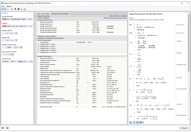
- Wyświetlanie odpowiednich wzorów użytych do sprawdzania warunków nośności (w tym odniesienie do zastosowanego równania z normy)
- 002172
- Ogólne informacje
- Projektowanie konstrukcji drewnianych RFEM 6
- Projektowanie konstrukcji drewnianych RSTAB 9
W porównaniu z modułem dodatkowym RF-/TIMBER Pro (RFEM 5/RSTAB 8) do rozszerzenia Projektowanie konstrukcji drewnianych dla programu RFEM 6/RSTAB 9 dodano następujące nowe funkcje:
- Oprócz Eurokodu 5, uwzględnione zostały inne międzynarodowe normy (SIA 265, ANSI/AWC NDS, CSA O86, GB 50005)
- Obliczanie ściskania prostopadle do włókien (ciśnienie na podporze)
- Wprowadzenie solwera wartości własnych do wyznaczania momentu krytycznego dla wyboczenia skrętnego (tylko EC 5)
- Definicja różnych długości efektywnych do obliczeń w normalnej temperaturze i odporności ogniowej
- Ocena naprężeń poprzez naprężenia jednostkowe (MES)
- Zoptymalizowane analizy stateczności dla prętów o zbieżnym przekroju
- Ujednolicenie materiałów dla wszystkich załączników krajowych (w bibliotece materiałów dostępna jest teraz tylko jedna norma „EN”)
- Wyświetlanie osłabień przekrojów bezpośrednio w renderingu
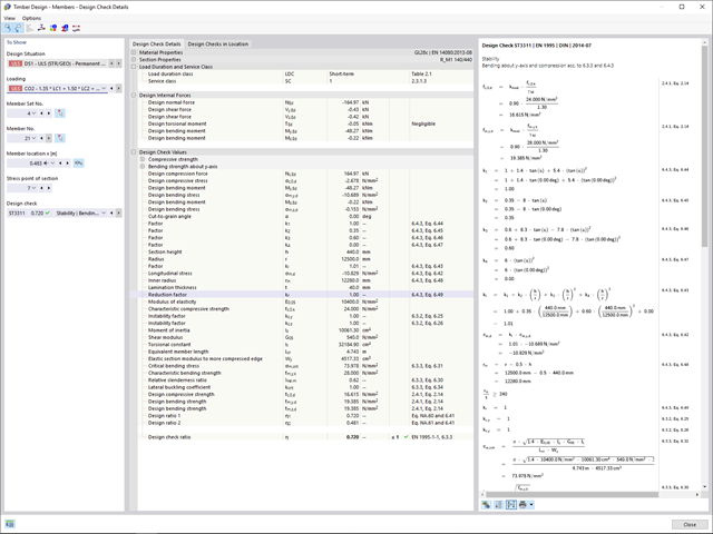
- Wyświetlanie odpowiednich wzorów użytych do sprawdzania warunków nośności (w tym odniesienie do zastosowanego równania z normy)
Dzięki oprogramowaniu Dlubal zawsze masz podgląd, niezależnie od tego, czy masz projekty z branży żelbetowej, stalowej, drewnianej, aluminiowej czy innej. Wzory do kontroli warunków projektowych zastosowane w obliczeniach są wyświetlane w przejrzysty sposób (wraz z odniesieniem do zastosowanego równania z normy). Te wzory do kontroli obliczeń można również uwzględnić w raporcie.
Przejdź do filmu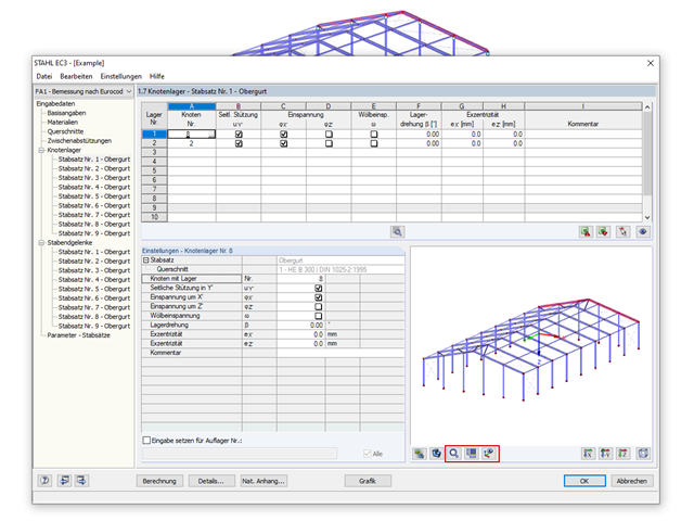
- 002317
- Ogólne informacje
- Projektowanie konstrukcji stalowych RFEM 6
- Projektowanie konstrukcji stalowych RSTAB 9
- Obliczanie ugięć i porównanie z normatywnymi lub ręcznie dostosowanymi wartościami granicznymi
- Uwzględnienie wygięcia wstępnego w analizie ugięcia
- W zależności od typu sytuacji obliczeniowej możliwe są różne wartości graniczne
- Ręczne dostosowywanie długości odniesienia i segmentacji według kierunku
- Obliczanie ugięć w odniesieniu do konstrukcji początkowej lub do konstrukcji odkształconej
- Dalsze szczegółowe obliczenia w zależności od wybranej normy obliczeniowej (np. ograniczenie oddychania środnika zgodnie z EN 1993-2)
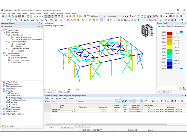
- Graficzne wyświetlanie wyników zintegrowane z RFEM/RSTAB; na przykład stopień wykorzystania wartości granicznej, odkształcenie lub ugięcie
- Pełna integracja wyników z protokołem wydruku programu RFEM/RSTAB

- 002318
- Ogólne informacje
- Projektowanie konstrukcji stalowych RFEM 6
- Projektowanie konstrukcji stalowych RSTAB 9
W programie RFEM/RSTAB istnieje możliwość wygenerowania, a następnie obliczenia kombinacji obciążeń lub wyników wymaganych dla stanu granicznego użytkowalności. Sytuacje obliczeniowe można wybrać do analizy ugięć w rozszerzeniu Projektowanie konstrukcji stalowych. Obliczone wartości odkształceń są odpowiednio określane w każdym miejscu pręta, w zależności od określonego wygięcia wstępnego i układu odniesienia. Na koniec można porównać te wartości odkształceń z wartościami granicznymi.
Czy wiecie, że...? Wartość graniczną deformacji można określić indywidualnie dla każdego elementu konstrukcyjnego w Konfiguracja stanu granicznego użytkowalności. Jako dopuszczalną wartość graniczną należy zdefiniować maksymalne odkształcenie w zależności od długości odniesienia. Poprzez zdefiniowanie podpór obliczeniowych można podzielić komponenty na segmenty w celu automatycznego określenia odpowiedniej długości odniesienia dla każdego kierunku obliczeń.
W zależności od położenia przydzielonych podpór obliczeniowych, rozróżnienie między belkami i wspornikami jest dokonywane automatycznie, dzięki czemu można odpowiednio określić wartość graniczną.
- 002319
- Ogólne informacje
- Projektowanie konstrukcji stalowych RFEM 6
- Projektowanie konstrukcji stalowych RSTAB 9
Zasady sprawdzania stanu granicznego użytkowalności można znaleźć w tabelach wyników w rozszerzeniu Projektowanie konstrukcji stalowych. Wyniki obliczeń można wyświetlić ze wszystkimi szczegółami w każdym miejscu obliczanych prętów. Ponadto dostępne są grafiki z wykresami wyników i stopni wykorzystania. Zapewnia to dobry przegląd sytuacji.
Wszystkie tabele wyników i grafiki można również zintegrować z globalnym protokołem wydruku programu RFEM/RSTAB jako część wyników wymiarowania stali. Dzięki temu można wyświetlać i dokumentować odkształcenia całej konstrukcji w ramach funkcji programu RFEM/RSTAB, niezależnie od rozszerzenia.
- 002320
- Ogólne informacje
- Projektowanie konstrukcji stalowych RFEM 6
- Projektowanie konstrukcji stalowych RSTAB 9
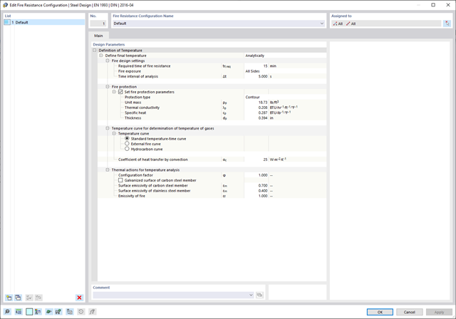
- Ręczne określenie temperatury krytycznej elementu lub automatyczne określenie temperatury elementu przez żądany czas
- Szeroki wybór krzywych pożaru: standardowa krzywa temperatura-czas, krzywa pożaru zewnętrznego, krzywa węglowodorów
- Ręczne dostosowywanie istotnych współczynników do określania temperatury stali
- Uwzględnienie cynkowania ogniowego elementów konstrukcyjnych przy określaniu temperatury stali
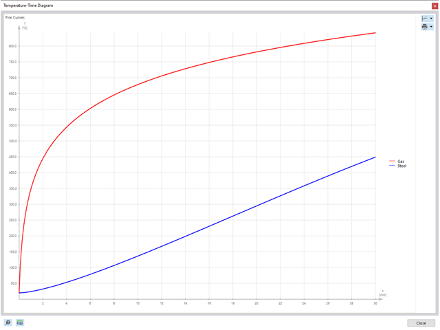
- Wyniki wykresu temperatura-czas dla temperatury gazu i stali
- Podczas określania temperatury można uwzględnić okładzinę ogniochronną w postaci obrysu lub okładziny skrzynkowej wykonanej z materiałów niezależnych od temperatury
- Wymiarowanie prętów ze stali węglowej lub nierdzewnej
- Obliczenia przekrojów i analiza stateczności (metoda prętów zastępczych) zgodnie z EN 1993-1-2, rozdz. 4.2.3
- Obliczenia przekrojów klasy 4 zgodnie z EN 1993-1-2, Załącznik E.
- 002321
- Ogólne informacje
- Projektowanie konstrukcji stalowych RFEM 6
- Projektowanie konstrukcji stalowych RSTAB 9
Programy do analizy statyczno-wytrzymałościowej RFEM/RSTAB oferują szereg zautomatyzowanych funkcji, które ułatwiają codzienną pracę. Jednym z nich jest automatyczne generowanie kombinacji obciążeń i wyników dla wyjątkowej sytuacji obliczeniowej w obliczeniach odporności ogniowej. Pręty, które mają zostać zwymiarowane wraz z odpowiednimi siłami wewnętrznymi, są importowane bezpośrednio z programu RFEM/RSTAB. Nie musisz'robić nic więcej. Program zachował również wszystkie informacje o materiale i przekroju.
Poprzez przypisanie konfiguracji odporności ogniowej do obliczanych prętów, użytkownik definiuje parametry istotne dla obliczeń odporności ogniowej. Tutaj można ręcznie określić krytyczną temperaturę stali w czasie projektowania. Temperaturę wyznaczaną przez program można określić automatycznie dla określonego czasu trwania pożaru. Do wyboru dostępne są różne krzywe temperatury pożaru i środki ochrony przeciwpożarowej. Można również wprowadzić dalsze szczegółowe ustawienia, takie jak zdefiniowanie ekspozycji na ogień ze wszystkich stron lub z trzech stron
- 002322
- Ogólne informacje
- Projektowanie konstrukcji stalowych RFEM 6
- Projektowanie konstrukcji stalowych RSTAB 9
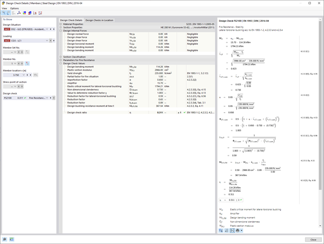
Weryfikacje wybranych prętów są przeprowadzane z uwzględnieniem decydującej temperatury elementu. W rozszerzeniu Projektowanie konstrukcji stalowych można przeprowadzić obliczenia przekrojów i analizy stateczności zgodnie z EN 1993-1-2, sekcja 4.2.3. Wszystkie niezbędne współczynniki i współczynniki redukcyjne są odpowiednio zapisywane i uwzględniane przy określaniu nośności.
Długości efektywne dla obliczeń pręta zastępczego są pobierane bezpośrednio z danych dotyczących wytrzymałości. Nie ma potrzeby'wprowadzania ich ponownie.
W każdym obliczeniu najpierw należy przeprowadzić klasyfikację przekroju. W przypadku przekrojów klasy 4 obliczenia są przeprowadzane automatycznie zgodnie z normą EN 1993-1-2, Załącznik E.
- 002323
- Ogólne informacje
- Projektowanie konstrukcji stalowych RFEM 6
- Projektowanie konstrukcji stalowych RSTAB 9
Po zakończeniu obliczeń, Dlubal Software przedstawia w przejrzysty sposób analizę odporności ogniowej wraz ze wszystkimi szczegółami wyników. Dzięki temu wyniki są zrozumiałe. Ponadto wyniki zawierają również wszystkie parametry wymagane do określenia temperatury elementu w czasie projektowania.
Rozkład temperatury w elemencie konstrukcyjnym można również ocenić za pomocą wykresu temperatura-czas.
Wszystkie tabele i grafiki wyników, w tym wyniki obliczeń stanu granicznego nośności i użytkowalności, można zintegrować z globalnym protokołem wydruku programu RFEM/RSTAB jako część wyników obliczeń konstrukcji stalowej.
- 002324
- Ogólne informacje
- Projektowanie konstrukcji stalowych RFEM 6
- Projektowanie konstrukcji stalowych RSTAB 9
W przypadku obliczeń zgodnie z Eurokodem 3 parametry załączników krajowych (NA) są zintegrowane dla następujących krajów:
-
DIN EN 1993-1-1/NA:2020-11 (Niemcy)
-
ÖNORM EN 1993-1-1/NA:2015-12 (Austria)
-
SN EN 1993-1-1/NA:2016-07 (Szwajcaria)
-
BDS EN 1993-1-1/NA:2015-10 (Bułgaria)
-
BS EN 1993-1-1/NA:2016-07 (Wielka Brytania)
-
CEN EN 1993-1-1/2015-06 (Unia Europejska)
-
CYS EN 1993-1-1/NA:2015-07 (Cypr)
-
CZE EN 1993-1-1/NA:2016-06 (Republika Czeska)
-
DS EN 1993-1-1/NA:2015-07 (Dania)
-
ELOT EN 1993-1-1/NA:2017-01 (Grecja)
-
EVS EN 1993-1-1/NA:2015-08 (Estonia)
-
HRN EN 1993-1-1/NA:2016-03 (Chorwacja)
-
I S. EN 1993-1-1/NA:2016-03 (Irlandia)
-
ILNAS EN 1993-1-1/NA:2015-06 (Luksemburg)
-
IST EN 1993-1-1/NA:2015-11 (Islandia)
-
LST EN 1993-1-1/NA:2017-01 (Litwa)
-
LVS EN 1993-1-1/NA:2015-10 (Łotwa)
-
MS EN 1993-1-1/NA:2010-01 (Malezja)
-
MSZ EN 1993-1-1/NA:2015-11 (Węgry)
-
NBN EN 1993-1-1/NA:2015-07 (Belgia)
-
NEN EN 1993-1-1/NA:2016-12 (Holandia)
-
NF EN 1993-1-1/NA:2016-02 (Francja)
-
NP EN 1993-1-1/NA:2009-03 (Portugalia)
-
NS EN 1993-1-1/NA:2015-09 (Norwegia)
-
PN EN 1993-1-1/NA:2015-08 (Polska)
-
SFS EN 1993-1-1/NA:2015-08 (Finlandia)
-
SIST EN 1993-1-1/NA:2016-09 (Słowenia)
-
SR EN 1993-1-1/NA:2016-04 (Rumunia)
-
SS EN 1993-1-1/NA:2019-05 (Singapur)
-
SS EN 1993-1-1/NA:2015-06 (Szwecja)
-
STN EN 1993-1-1/NA:2015-10 (Słowacja)
-
TKP EN 1993-1-1/NA:2015-04 (Białoruś)
-
UNE EN 1993-1-1/NA:2016-02 (Hiszpania)
-
UNI EN 1993-1-1/NA:2015-08 (Włochy)
- 002325
- Ogólne informacje
- Projektowanie konstrukcji stalowych RFEM 6
- Projektowanie konstrukcji stalowych RSTAB 9
Należy przeprowadzić obliczenia odporności ogniowej ze zredukowaną nośnością na podstawie temperatury elementu, wyznaczonej automatycznie w czasie projektowania. Można to określić automatycznie na podstawie różnych krzywych temperatury w programie (standardowa krzywa temperatura-czas, krzywa pożaru zewnętrznego, krzywa węglowodorów). W przypadku innych typów określania temperatury można również ręcznie określić temperaturę, która zostanie zastosowana w obliczeniach. Można to na przykład określić zgodnie z parametryczną krzywą temperatura-czas z normy DIN EN 1991-1-2 lub z protokołu ochrony przeciwpożarowej.
- 002326
- Ogólne informacje
- Projektowanie konstrukcji stalowych RFEM 6
- Projektowanie konstrukcji stalowych RSTAB 9
Temperatura elementu, która ma być zastosowana w czasie projektowania, jest określana automatycznie. Współczynniki używane do określania temperatury można dostosowywać. Na tym etapie najlepiej jest również wybrać cynkowanie ogniowe. Zgodnie z wytyczną DASt 027 „Wyznaczanie temperatury elementów ze stali ocynkowanej ogniowo na wypadek pożaru“, stosowana jest niższa emisyjność powierzchni stalowej, aż do osiągnięcia określonej temperatury granicznej. Ogólnie rzecz biorąc, daje to niższą temperaturę, a tym samym bardziej korzystne obliczenia odporności ogniowej.
- 002327
- Ogólne informacje
- Projektowanie konstrukcji stalowych RFEM 6
- Projektowanie konstrukcji stalowych RSTAB 9
Na podstawie danych wejściowych można automatycznie określić decydującą temperaturę elementu w momencie przeprowadzania analizy. W takim przypadku można szczegółowo prześledzić krzywą temperatury w funkcji czasuwykres temperatura-czas.
- 002328
- Ogólne informacje
- Projektowanie konstrukcji stalowych RFEM 6
- Projektowanie konstrukcji stalowych RSTAB 9
Czy przejrzysty układ jest dla Ciebie ważny? Program zapewnia przejrzysty przegląd wszystkich przeprowadzonych kontroli obliczeń dla danej normy obliczeniowej. Dla każdej kontroli obliczeń konieczne jest określenie kryterium obliczeniowego. Dostępne są również szczegóły obliczeń, w tym wartości początkowe, wyniki pośrednie i wyniki końcowe. W tym miejscu znajduje się również okno informacyjne, w którym szczegółowo przedstawiony jest przebieg obliczeń wraz z zastosowanymi wzorami, standardowymi źródłami i wynikami.
- 002329
- Ogólne informacje
- Projektowanie konstrukcji stalowych RFEM 6
- Projektowanie konstrukcji stalowych RSTAB 9
Wyniki obliczeń można znaleźć bezpośrednio w rozszerzeniu Projektowanie konstrukcji stalowych. Są one tam dostępne w formie tabelarycznej. Rozkład stopni wykorzystania można również wyświetlić graficznie. Zarówno w tabeli, jak i w postaci graficznej dostępne są liczne opcje filtrowania. Dzięki temu można wyświetlać żądane warunki projektowe według stanu granicznego lub typu obliczeń.
- 002330
- Ogólne informacje
- Projektowanie konstrukcji stalowych RFEM 6
- Projektowanie konstrukcji stalowych RSTAB 9
W zależności od kierunku można indywidualnie zdefiniować wszystkie długości odniesienia, które muszą zostać uwzględnione podczas obliczeń wartości granicznej ugięcia, a także które segmenty mają zostać sprawdzone. W tym celu należy zdefiniować podpory obliczeniowe w węzłach pośrednich pręta i przydzielić je do odpowiedniego kierunku na potrzeby analizy odkształceń. W ten sposób tworzone są segmenty, w których można zdefiniować wygięcie wstępne dla każdego kierunku i segmentu.