61 Wyniki
Wyświetl wyniki:
Sortuj według:

W celu obliczenia odporności ogniowej powierzchni drewnianych można wyświetlić wykres zwęglania w zależności od czasu trwania pożaru.
Wykres ten można również wydrukować w raporcie.

Tabela wyników modelu budynku 'Wyniki według kondygnacji' przedstawia środek ciężkości przypadków obciążeń i kombinacji obciążeń. Oprócz obciążenia stałego uwzględniane są również obciążenia pionowe odpowiednich przypadków obciążeń i kombinacji obciążeń.
W celu wyświetlenia środka ciężkości z uwzględnieniem wybranego obciążenia można również użyć okna dialogowego 'Środek ciężkości oraz Informacje o wybranych obiektach.

W rozszerzeniu Model budynku można zdefiniować właściwości ścian usztywniających i belek-ścian dla odpowiednich rozszerzeń.

Do modelowania kondygnacji, w przypadku płyt można wykorzystać opcję "Tarcza podatna".
Zasadniczo ta opcja modelowania wybiera to samo podejście, co w przypadku modelowania kondygnacji typu "Sztywna przepona". W przeciwieństwie do sztywnej przepony, sprzężenie węzłowe nie jest przeprowadzane od środka ciężkości do każdego węzła ES. W ten sposób możliwe jest uwzględnienie elastyczności płyty.

- 002842
- Ogólne informacje
- Analiza naprężeniowo-odkształceniowa RFEM 6
- Analiza naprężeniowo-odkształceniowa RSTAB 9
W rozszerzeniu Analiza naprężeniowo-odkształceniowa można użyć opcji, aby określić zależne od znaku naprężenia graniczne za pomocą składowej naprężenia.

- 002829
- Ogólne informacje
- Analiza naprężeniowo-odkształceniowa RFEM 6
- Analiza naprężeniowo-odkształceniowa RSTAB 9
W rozszerzeniu Analiza naprężeniowo-odkształceniowa można zdefiniować cykl naprężeń granicznych zależny od elementu i uwzględnić go w obliczeniach.

Podczas generowania ścian usztywniających i belek-ścian można przydzielać nie tylko powierzchnie i komórki, ale także pręty.

W obliczeniach modelu budynku można pominąć otwory o określonej powierzchni. Funkcję tę można aktywować w ustawieniach globalnych kondygnacji budynku. Pojawi się komunikat ostrzegający, że otwory zostały pominięte.

Model budynku jest obliczany w dwóch etapach:
- Globale 3D-Berechnung des Gesamtmodells, in welchem die Decken als starre Ebene (Diaphragma) oder als Biegeplatte modelliert werden
- Lokale 2D-Berechnung der einzelnen Geschossdecken
Die Ergebnisse der Stützen und Wände aus der 3D-Berechnung und die Ergebnisse der Decken aus der 2D-Berechnung werden nach der Berechnung in einem einzigen Modell zusammengefasst. Dadurch muss zwischen dem 3D-Modell und der einzelnen 2D-Modellen der Decken nicht gewechselt werden. Der Anwender arbeitet nur mit einem Model, spart wertvolle Zeit und vermeidet eventuelle Fehler beim händischen Datenaustausch zwischen dem 3D-Modell und der einzelnen 2D-Decken-Modelle.
Die vertikalen Flächen im Modell können vom Nutzer in Schubwände (Shear Walls) und Öffnungsstürze (Sprandels) geteilt werden. Aus diesen Wandobjekten erzeugt das Programm automatisch interne Ergebnisstäbe, so dass diese dann nach der gewünschten Norm im Add-On Betonbemessung für RFEM 6 als Stäbe bemessen werden können.

Istnieje możliwość wymiarowania powierzchni z uwagi na warunki pożarowe przy użyciu metody zredukowanego przekroju. Redukcja jest stosowana na grubości powierzchni. Kontrolę obliczeń można przeprowadzić dla wszystkich materiałów drewnianych, które są dopuszczone dla obliczeń.
W przypadku drewna klejonego krzyżowo, w zależności od rodzaju kleju, można wybrać, czy możliwe jest odpadanie poszczególnych zwęglonych części warstwy, a tym samym, czy można spodziewać się zwiększonego zwęglenia w niektórych obszarach warstwy.

Ściany usztywniające i belki-ściany z modelu budynku są dostępne jako niezależne obiekty w rozszerzeniach. W ten sposób możliwe jest szybsze filtrowanie obiektów w wynikach oraz tworzenie lepszej dokumentacji w raporcie.

Za pomocą generatora kondygnacji w rozszerzeniu Model budynku można automatycznie tworzyć kondygnacje budynku w zależności od topologii modelu.

W przypadku analizy spektrum odpowiedzi modeli budynków można wyświetlić współczynniki wrażliwości dla kierunków poziomych według kondygnacji.
Dzięki tym kluczowym wartościom można zinterpretować wrażliwość na efekty stateczności.
.png?mw=640&hash=403c565ab80c4dd45c2d1356634fb74a90428b70)
W bibliotece konstrukcji warstwowych dostępni są następujący producenci drewna klejonego krzyżowo:
- Binderholz (USA)
- KLH (USA, CAN)
- Kalesnikoff (USA, CAN)
- Nordic Structures (USA, CAN)
- Mercer Mass Timber
- SmartLam
- Sterling Structural
- Konstrukcje nośne wymienione w Lignatec wydanie 32 "Drewno klejone krzyżowo z produkcji szwajcarskiej"
Wczytanie konstrukcji z biblioteki konstrukcji warstw powoduje automatyczne przejęcie wszystkich istotnych parametrów. Biblioteka jest stale aktualizowana.

- 002687
- Ogólne informacje
- Projektowanie konstrukcji drewnianych RFEM 6
- Projektowanie konstrukcji drewnianych RSTAB 9
Rozszerzenie Projektowanie konstrukcji drewnianych dla programu RFEM 6/RSTAB 9 ma wiele zastosowań i łączy w sobie wiele dodatkowych elementów. [*S16332764*] Rozszerzenie Wymiarowanie drewna dla RFEM 6

W przypadku elementów w modelach budynków dostępnych jest kilka narzędzi do modelowania:
- Linia pionowa
- Słup
- Ściana
- Belka
- Strop prostokątny
- Płyta wielokątna
- Prostokątny otwór w stropie
- Wielokątny otwór w stropie
Ta funkcja umożliwia definicję elementów na płaszczyźnie podłoża (na przykład z warstwą tła) z powiązanym tworzeniem wielu elementów w przestrzeni.

Korzystając z kondygnacji typu "Tylko przenoszenie obciążenia", można uwzględnić w rozszerzeniu Model budynku stropy bez wpływu sztywności do i z płaszczyzny. Ten typ elementu zbiera obciążenia na stropie i przenosi je na elementy nośne modelu 3D. Daje to możliwość symulacji w modelu 3D elementów drugorzędnych, takich jak np. ruszt i inne podobne elementy rozkładu obciążenia, bez dalszych efektów.

Czy wiecie, że...? W podporach obliczeniowych można teraz zdefiniować śruby z pełnym gwintem jako poprzeczne elementy wzmacniające ściskanie dla obliczenia "Ściskania w poprzek włókien". Śruby są sprawdzane pod kątem wciśnięcia i wyboczenia.
Dodatkowo sprawdzana jest nośność na ścinanie w płaszczyźnie wierzchołka śruby. Kąt rozłożenia obciążenia można uwzględnić liniowo poniżej 45° lub nieliniowo (zgodnie z Bejtka, I. (2005). Verstärkung von Bauteilen aus holz mit vollgewindeschrauben. KIT Scientific Publishing.

W programach RFEM i RSTAB można wymiarować pręty przy użyciu materiału typu "Fornir klejony warstwowo". Dostępni są następujący producenci:
- Pollmeier (Baubuche)
- Metsä (kerto LVL)
- STEICO
- Stora Enso
W konfiguracji stanu granicznego nośności można uwzględnić współczynniki wytrzymałości w celu zwiększenia wytrzymałości. Niezależnie od tego współczynniki zmniejszające wytrzymałości są uwzględniane automatycznie. Wypróbuj teraz!
Przejdź do filmu
Można ocenić przekroje wynikowe dla obliczeń powierzchni drewnianych w sposób graficzny. Z jednej strony w grafice programu RFEM, az drugiej strony w oknie historii wyników. Przekroje można umieszczać w dowolnym miejscu w celu szczegółowej oceny wyników obliczeń.

W przypadku powierzchni drewnianych o grubości "Stała" uwzględniany jest współczynnik zarysowania kcr, a tym samym negatywny wpływ rys na wytrzymałość na ścinanie.

W programie RFEM zaimplementowano bibliotekę płyt z drewna klejonego krzyżowo, z której można importować konstrukcje warstwowe różnych producentów (np. Binderholz, KLH, Piveteaubois, Södra, Züblin Timber, Schilliger, Stora Enso). Oprócz grubości i materiałów warstw podane są również informacje o redukcji sztywności i łączeniu wąskich boków.
Przejdź do filmu
Rozszerzenie Projektowanie konstrukcji drewnianych dla RFEM umożliwia wymiarowanie prętów i powierzchni zgodnie z Eurokodem 5, SIA 265 (norma szwajcarska), CSA O86 (norma kanadyjska) lub ANSI/AWC NDS (norma amerykańska), np. drewno klejone krzyżowo, drewno klejone warstwowo, drewno iglaste, materiały drewnopochodne itp.
Przejdź do filmu
Aktywowałeś rozszerzenie Model budynku ? Bardzo dobrze! Możesz wyświetlić środek sztywności w tabeli i w formie graficznej. Użyj go na przykład do analizy dynamicznej.
- 002496
- Ogólne informacje
- Projektowanie konstrukcji drewnianych RFEM 6
- Projektowanie konstrukcji drewnianych RSTAB 9
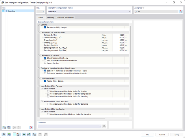
Występuje skręcanie? W takim przypadku to Ty decydujesz o sposobie przeprowadzenia obliczeń. Do dyspozycji masz następujące opcje:
- Zezwól na dalsze obliczenia, jeżeli naprężenie styczne od skręcania nie przekracza wartości granicznej
- Wymiarowanie zgodnie z Timber Construction Manual, 4.6
- Ignorowanie skręcania

W programie RFEM 6 możliwe jest definiowanie spoin liniowych między powierzchniami i obliczanie naprężeń w spoinie za pomocą rozszerzenia Analiza naprężeniowo-odkształceniowa.
Dostępne są następujące typy połączeń:
- połączenie stykowe
- Złącze narożne
- Złącze zakładkowe
- Złącze teowe
W zależności od typu połączenia dostępne są następujące typy spoin:
- Pojedynczy kwadrat
- Podwójny
- Podwójny ukos
- Spoina typu V
- Spoina typu 2 V
- Spoina typu U
- Spoina typu 2 U
- Spoina typu J
- Spoina typu 2 J

- 002133
- Ogólne informacje
- Projektowanie konstrukcji drewnianych RFEM 6
- Projektowanie konstrukcji drewnianych RSTAB 9
- Szeroki wybór przekrojów, takich jak przekroje prostokątne, kwadratowe, teowe, okrągłe, złożone, nieregularne przekroje parametryczne i wiele innych (przydatność do obliczeń zależy od wybranej normy)
- Wymiarowanie drewna klejonego krzyżowo (CLT)
- Wymiarowanie materiałów drewnopochodnych i drewna klejonego warstwowo zgodnie z EC 5
- Wymiarowanie prętów o zmiennym przekroju (metoda zgodna z normą)
- Możliwe jest dostosowanie istotnych współczynników obliczeniowych i parametrów normowych
- Elastyczność dzięki szczegółowym opcjom ustawień dla podstawy i zakresu obliczeń
- Szybkie i przejrzyste wyświetlanie wyników dla globalnej oceny ich rozkładu na konstrukcji po zakończeniu obliczeń
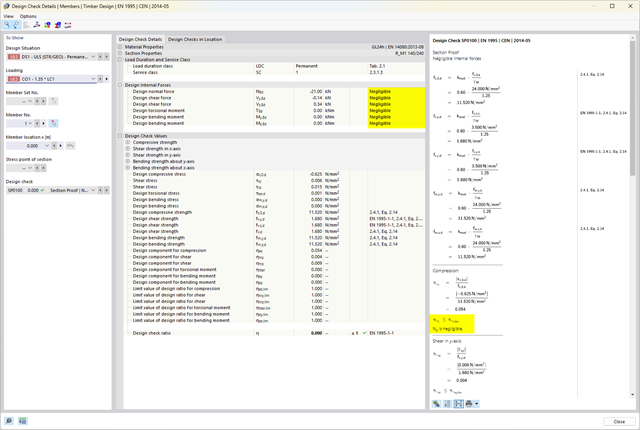
- Szczegółowe wyniki obliczeń i niezbędne wzory (jasna i łatwa do zweryfikowania ścieżka wyników)
- Przejrzyste zestawienie wyników w formie numerycznej w stosownych oknach oraz możliwość ich graficznego przedstawienia na konstrukcji
- Integracja wyników z protokołem wydruku programu RFEM/RSTAB
- 002134
- Ogólne informacje
- Projektowanie konstrukcji drewnianych RFEM 6
- Projektowanie konstrukcji drewnianych RSTAB 9
- Wymiarowanie elementów rozciąganych, ściskanych, zginanych, ścinanych, skręcanych i poddanych połączonemu działaniu tych sił wewnętrznych
- Uwzględnienie podcięcia
- Obliczanie ściskania prostopadle do włókien na podporach końcowych i pośrednich z (EC 5) i bez elementów wzmacniających (śruby z pełnym gwintem)
- Opcjonalna redukcja siły tnącej na podporze
- Wymiarowanie prętów zakrzywionych i zbieżnych
- Uwzględnianie wyższych wytrzymałości dla podobnych elementów, które znajdują się blisko siebie (współczynnik ksys wg EN 1995-1-1, 6.6(1)-(3))
- Możliwość zwiększenia nośności na ścinanie dla drewna iglastego zgodnie z DIN EN 1995‑1‑1:NA NDP do 6.1.7(2)
- 002135
- Obliczenia
- Projektowanie konstrukcji drewnianych RFEM 6
- Projektowanie konstrukcji drewnianych RSTAB 9
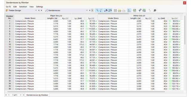
- Analiza stateczności dla wyboczenia giętnego, wyboczenia skrętnego i wyboczenia giętno-skrętnego przy ściskaniu
- Import długości efektywnych z obliczeń przy użyciu rozszerzenia Stateczność konstrukcji
- Graficzne wprowadzanie i kontrola zdefiniowanych podpór węzłowych oraz długości efektywnych w celu analizy stateczności
- Określanie długości zastępczych prętów o zbieżnym przekroju
- Uwzględnienie położenia stężenia zwichrzenia
- Analiza zwichrzenia elementów poddanych obciążeniu momentem
- W zależności od normy istnieje wybór między wprowadzaniem wartości Mcr przez użytkownika, metodą analityczną z normy lub wykorzystaniem wewnętrznego solwera wartości własnych
- Uwzględnienie panelu usztywniającego i ograniczenia obrotu podczas korzystania z solwera wartości własnych
- Graficzne przedstawienie postaci własnej w przypadku zastosowania solwera wartości własnych
- Analiza stateczności elementów konstrukcyjnych ze ściskaniem i naprężeniem zginającym, w zależności od normy obliczeniowej
- Przejrzyste obliczenia wszystkich niezbędnych współczynników, takich jak współczynniki uwzględniające rozkładu momentów lub współczynniki interakcji
- Alternatywne uwzględnienie wszystkich wpływów dla analizy stateczności podczas określania sił wewnętrznych w programie RFEM/RSTAB (analiza drugiego rzędu, imperfekcje, redukcja sztywności, ewentualnie w połączeniu z rozszerzeniem Skręcanie skrępowane (7 stopni swobody))

- 002372
- Ogólne informacje
- Projektowanie konstrukcji drewnianych RFEM 6
- Projektowanie konstrukcji drewnianych RSTAB 9
- Dowolna definicja czasu zwęglania
- W przypadku konstrukcji powierzchniowych (drewno klejone krzyżowo) można obliczyć z przyczepnością lub bez
- Bezpłatna, zdefiniowana przez użytkownika specyfikacja parametrów pożaru
- Uwzględnienie różnych długości efektywnych do obliczania odporności ogniowej
- Opcjonalne obliczenia dla 'ściskania w poprzek włókien'
- Zintegrowane z RFEM/RSTAB graficzne wyświetlanie wyników, np. B. Stopień wykorzystania
- Pełna integracja wyników z protokołem wydruku programu RFEM/RSTAB